












Most people meet the shielded-vs-unshielded question the way a mechanic meets a new tool: holding a worn sensor that just stopped working, next to a machine that has to run today. The sensor is out, the mounting hole is there, and the spare-parts drawer holds something that looks almost the same but isn’t. If that sounds familiar, this guide is written for you, and for anyone who answers those questions for a living.
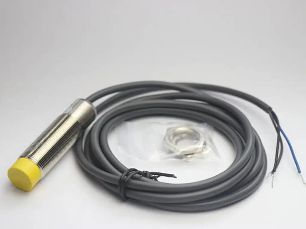
Shielded vs Unshielded Proximity Sensor: Spot the Difference at a Glance
A shielded proximity sensor is also called a flush sensor; an unshielded one is called non-flush. Both are inductive proximity switches: they detect metal objects without touching them, and their differences come down to one design choice inside the housing. This article is only about that inductive type. Capacitive, photoelectric and ultrasonic sensors are a different technology family; if you have one of those on your bench, stop here and find the right family first.
One clarification before the practical part. “Shielded” here means the sensor’s magnetic-field shielding, a metal structure around the sensing coil. It has nothing to do with shielded cable, and it is not electromagnetic-interference (EMI) shielding in the cable sense. Confusing those two is the most common way people misread specifications.
Here is how to tell which type you are holding. No multimeter needed, just your eyes:
| Check this | Shielded (flush) | Unshielded (non-flush) |
|---|---|---|
| End of the sensing head | Thread runs all the way to the sensing face; the barrel looks uniform | A plastic nose sticks out past the threaded barrel, so the head looks longer |
| Head length vs the same-diameter counterpart | Shorter | Longer (the exposed coil nose adds length) |
| Where the field comes out | Only the sensing face | The face plus the sides of the nose |
| Mounting rule | Can sit flush, even embedded in metal | Needs open space around the nose: no surrounding metal |
| Typical body sizes | M8 / M12 / M18 / M30 (and rectangular) | Same M8 / M12 / M18 / M30 sizes |
Fastest rule of thumb: if the head pokes out of the threads, it is unshielded. If the face is flush with the thread end, it is shielded. Compare it side by side with any other sensor of the same diameter and the difference is obvious.
Knowing which one you hold matters, because the two behave differently around metal. That is exactly what the next section explains.
Why They Behave Differently: Flush, Non-Flush, and the Third Design
Inside the barrel, an inductive sensor generates a magnetic field from a coil. A shielded sensor wraps that coil in a metal shield, so the magnetic flux concentrates in front of the sensing face. An unshielded sensor leaves the coil open at the nose, so the flux spreads forward and sideways.
That one structural difference drives everything downstream:
- Shielded sensors can be embedded in metal. Because their field only reaches forward, surrounding metal (a mounting block, a machine frame, neighboring steel) does not disturb them. This is why shielded types are also called embeddable.
- Unshielded sensors cannot sit flush in metal. Their sideways field reaches the metal around them. Put one in a metal pocket and the metal itself stays inside the detection field. The field gets preloaded by the mounting structure, so the sensor triggers earlier than rated, behaves unpredictably, or never switches off.
- Shielding costs sensing distance. Focusing the field forward means the same diameter reaches a shorter rated distance than the unshielded version. The shorter range is not a defect. It is the price of being embeddable.
There is also a third design worth knowing about: semi-flush (quasi-flush) sensors. They embed like a flush sensor but still need a ring of metal-free space around the sensing face. In protection and in range they sit between the two, and they solve a handful of installations where a true flush sensor is too short-range and a non-flush one cannot fit.
One boundary to keep in mind: this whole mechanism is about metal surroundings. If your sensor is mounted in plastic or on an open bracket, the two types behave far more alike. The unshielded design still reaches further, but there is no mounting penalty. It is in metal-heavy machines that the difference decides everything.
Flush-Mount or Not? Match the Installation, Avoid the Three Failure Modes
The choice is rarely about which sensor is “better”. It is about what your installation allows. Walk through your mounting position first, then let the table pick the type:
| Your installation | Best choice | What goes wrong if you ignore it |
|---|---|---|
| Sensor embedded in a metal block, slide, or frame | Shielded (flush) | An unshielded sensor here triggers early or sticks on: the metal mount preloads the field |
| Metal guard or pocket around the sensor, but the nose can protrude | Shielded, or semi-flush if you need more range | Exposed nose gets hit by the target on its way past |
| Machine tooling, robot grippers, tight multi-sensor clusters | Shielded (flush) protects the face | An exposed nose gets struck and damaged; targets hit a protruding sensor |
| Open bracket or stand with nothing metal nearby, maximum range needed | Unshielded (non-flush) | A shielded sensor here just wastes reachable distance |
| Conveyor gaps, tank levels, large travel detection | Unshielded | Side field picks up adjacent metal and false-triggers |
| Multiple sensors side by side on a metal rail | Shielded, spaced about 2× diameter or more | Unshielded units need roughly 3× diameter spacing or they cross-trigger |
Mounting decision shortcut: metal all around the face points to shielded. Open space plus a need for every millimeter of range points to unshielded. In between, semi-flush.
Now the part repair people learn the hard way. Mount the wrong type and the machine does not quietly degrade. It fails in one of three recognizable ways:
False triggering
Symptom: output fires when the target is nowhere near, or fires earlier than before. Likely cause: sideways field preloaded by mounting metal or by a metal chip pile. Action: check what metal sits around the nose; if the sensor is pocketed in metal, replace it with a shielded type or give the nose clearance
Stuck on (always ON)
Symptom: output never releases; the LED stays lit. Likely cause: the surrounding structure itself is inside the field. An unshielded sensor flush-mounted in a metal bore is the classic case. Action: pull the sensor out of the pocket; if the bore is the requirement, fit a shielded unit
Collision damage
Symptom: dents, bent noses, cracked faces, usually on sensors that stick out into a travel path. Action: if targets or operators can physically reach the head, flush-mount a shielded type so nothing protrudes beyond the surface
Note what all three share: they are mounting failures, not sensor failures. In two of them the sensor was fine. It was the wrong type for the pocket it sat in. That is why every replacement should start with a question about the hole, not about the part number. And when the application needs a specific reach, the numbers in the next section settle which type can deliver it.
Sensing Distance by Diameter: Paired Numbers for Shielded and Unshielded Sensors
Rated sensing distance (Sn) is measured with a standard iron target under defined test conditions. For cylindrical sensors that is typically a square iron piece (8×8×1 mm for the small bodies, larger test pieces for bigger diameters), with a tolerance band of roughly ±10%. Catalogue numbers are rated distances. Omron’s technical guides advise treating about 70-80% of the rated value as the stable, dependable working distance in real temperature and voltage conditions.
Across manufacturers, the same body diameter is offered in matched shielded and unshielded versions, and the ranges are remarkably consistent:
| Body diameter | Shielded (flush), typical Sn | Unshielded (non-flush), typical Sn |
|---|---|---|
| M8 | 1.5-2 mm | 2-4 mm |
| M12 | 2-4 mm | 4-8 mm |
| M18 | 5-8 mm | 8-16 mm |
| M30 | 10-15 mm | 15-30 mm |
This table is why the “which one reaches farther” answer is always the same: at any given diameter, the unshielded version reaches roughly 1.5-2× the shielded version’s distance, often exactly double. An M12 pair of 2 mm flush and 4 mm non-flush is a common combination.
The rule to remember: one body diameter, two range answers. The flush version is the short-range, embeddable answer; the non-flush version is the long-range, open-space answer. Match your hole first, then read your range off the row for that diameter.
You will also see sources disagree about how much longer unshielded sensors reach. One reputable vendor FAQ says 25-100% greater; others quote “1.5-2×”. Both are honest, and both are incomplete. Manufacturers do not build every diameter pair to the same ratio, so one catalogue’s pair may be 5 mm vs 8 mm (1.6×) while another’s is 2 mm vs 4 mm (exactly 2×). Memorize the paired table for your diameter instead of a multiplier, and when a specific machine is involved, read the actual datasheet values.
One body diameter, two range answers
The flush version is the short-range answer for metal pockets; the non-flush version is the long-range answer for open space.
Match the hole first — then the range.
Target Metal Changes the Game: Derating That Compounds the Difference
Rated distances are measured against mild steel, which is the 1.00 reference. Change the target metal and the effective distance shrinks, sometimes a lot. Correction factors vary by manufacturer and by sensor family, but the magnitudes are consistent. Aluminum commonly comes in around 0.3-0.5 (roughly a third to half of the steel rating). Brass lands around 0.4-0.5, and austenitic stainless steel (grades like 304/316) around 0.6-0.85. The stainless figure depends strongly on grade and surface condition, while magnetic stainless grades behave closer to mild steel.
This derating is where the paired-range table starts to matter in practice. Take an M18 pair: a shielded 5 mm unit derated to 40% reaches about 2 mm of real aluminum detection. An unshielded 8 mm unit on the same target keeps about 3 mm, and its larger absolute range absorbs the metal penalty better. If your target is aluminum, brass or stainless, start from the derated distance, not from the catalogue number.
Clearance Rules for Non-Flush Mounts: the Numbers to Ask For
If the choice lands on unshielded, the mounting rules become a spec sheet of their own. Practical rules of thumb used across the industry:
- Metal-free zone around the sensing nose: allow clearance in every direction around the head, commonly on the order of 2× the rated distance behind and around the face, and no opposing metal closer than about 3× the rated distance.
- Side-by-side spacing: neighboring unshielded sensors typically need about 3× their diameter between them; shielded sensors get away with about 2×.
- Ask the supplier for these numbers.
Red flag: a competent supplier can quote the metal-free depth and the recommended spacing for the exact model they sell. If they cannot tell you these numbers, treat that as a reason to look elsewhere.
None of these are universal constants. They vary by family and by manufacturer, which is precisely why they belong on your check-list of questions instead of in your memory.
Replacing a Proximity Sensor? Classify the Old One First
Replacement is where this topic actually earns its keep. The mounting hole is already drilled, and the old sensor’s part number may be worn off. Work the problem in four steps:
Classify the old unit: plastic nose past the threads means unshielded; face flush with the threads means shielded. If the old unit was mounted in a metal pocket, it was almost certainly shielded. Check that it really was, because mismatched replacements are how pockets eat non-flush sensors.
Read the markings: most inductive sensors print the body diameter and the rated distance into the model code (a “12” for M12, plus a distance number such as 4 mm). The diameter and the old distance pin down the row of the paired table you need.
Decide whether to change type: the hole does not force you to stay with the same type. If the machine needs more reach and the mounting has open space, an unshielded unit of the same diameter is a legitimate upgrade. Engineering discussions in the field regularly move from a shielded 1.5 mm M8 to a 4 mm non-flush M8 on the same thread. But if the sensor sits in a metal bore or behind a guard, the flush type is not optional: longer reach only counts if the mounting allows it.
Confirm the electrical side before the mechanical one: output type (NPN vs PNP), wiring (2-wire vs 3-wire), supply voltage and NO/NC logic must match the controller. Get that wrong and the perfect sensor still will not run. Output selection has its own rules, covered in our separate guide on NPN vs PNP sensor outputs.
The single most common replacement failure is skipping step 3: choosing a longer-range sensor without checking that its mounting rules still fit the hole. Range and mounting are two separate constraints. A non-flush sensor with wonderful reach will false-trigger the moment it is pocketed in the metal it was meant to watch.
Range, mounting, output type: five minutes of spec confirmation before you order saves a return trip.
For Distributors: Stock and Quote Paired Ranges, Not Categories
If you supply sensors to repair shops and maintenance teams, this article describes your customers’ orders better than it describes a classroom topic. Listen to how the requests actually arrive: a photo of a worn sensor, a scribbled diameter, “it keeps triggering when nothing’s near it”, or “I need the same one but with more reach”. Nobody phones a distributor asking for “a non-flush unshielded inductive proximity sensor”. They describe a hole, an old part, and a symptom.
That is the whole business case for the paired table. The maintenance market’s order language is hole + old part, and the paired ranges are the bridge from that language to a part number. Every common body diameter resolves into the same two answers: the flush short-range unit for metal pockets, and the non-flush longer-range unit for open space. A repair quote becomes a two-minute routine: classify the old unit, measure the diameter, offer the matching pair.
Stock the pairs, quote in pairs, and teach your customers to ask for a range — that is how repair-market orders actually get placed.
We catalogue inductive proximity sensors exactly this way. Our range pairs each common body size: an M12 flush version rated at 2 mm sits alongside a non-flush M12 of the same family rated at 4 mm (±10% on standard iron targets), and M8, M18 and M30 are covered the same way. A replacement inquiry that starts from a hole and an old part lands on a concrete model instead of a category. If you need the mounting and metal-free figures for a specific model rather than a rule of thumb, our selection support engineers will confirm them against the actual datasheet, and the full shielded and unshielded inductive proximity sensor range is online for comparison.
A customer who can say “I need an M12, flush, 2 mm” has already bought the sensor. They just do not know it yet.
Stock the Pairs Your Customers Ask For
Flush and non-flush versions across M8–M30, with the mounting numbers confirmed against the datasheet before you order.
Request the proximity sensor catalogReferences
- Omron Industrial Automation. “Proximity Sensors — Explanation of Terms.” Technical guide. https://www.ia.omron.com/support/guide/41/explanation_of_terms.html
- AutomationDirect. “What Is the Difference Between a Shielded and Unshielded Proximity Sensor?” FAQ #458. https://support.automationdirect.com/faq/showfaq.php?id=458
- autosen. “Correction Factors for Inductive Sensors.” Technical article. https://autosen.com/en/Category/ListArticles/323
- RS Components / DesignSpark. “What Is the Difference Between Shielded & Unshielded Proximity Sensors?” https://www.rs-online.com/designspark/what-is-the-difference-between-shielded-flush-mountable-and-non-shielded-non-flush-inductive-proximity-sensors
- Sense the World. “Inductive Proximity Sensors: The Unspoken Truths from Two Decades in the Trenches.” https://www.sense-the-world.com/tech-hub/5450.html
- Eng-Tips Forums. “Looking to Replace Inductive Prox Switch in Demanding Application.” Thread discussion, 2025. https://www.eng-tips.com/threads/looking-to-replace-inductive-prox-switch-in-demanding-application.528519/



 English
  Arabic
  Turkish
  Russian
  Spanish
  French
  Indonesian
  Portuguese
  Thai
Thai  Vietnamese