












Ask ten automation suppliers which sensor is “better” (proximity sensor vs photoelectric sensor), and you will get ten confident, contradictory answers. Ask the machine instead, and the argument mostly disappears. A 5 m photoelectric beam is not better than a 5 mm inductive unit; it is a different answer to a different detection point. What most comparison articles skip is the order of operations: two physical media, and a handful of constraints that eliminate one of them before you ever compare catalogs. That order is what this guide walks through, and the same order decides which sensor actually survives on your line.
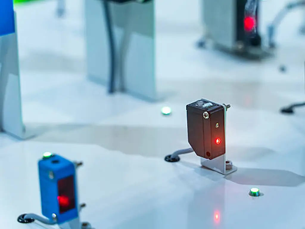
Proximity Sensor vs Photoelectric Sensor: Two Names, Two Physical Media
The naming is the first trap, so clear it early. Proximity sensors sense through a physical field: an electromagnetic field (inductive), an electrostatic field (capacitive), or a magnetic field (Hall-effect and reed types). Photoelectric sensors sense through light: an emitter sends a modulated beam, and the target is detected when it reflects, interrupts, or returns that beam.
Why do you see the phrase “photoelectric proximity sensor” in catalogs? Because some manufacturers treat photoelectric as a long-range branch of proximity sensing, while others reserve “proximity” strictly for inductive, capacitive, and magnetic types. It is a vendor classification disagreement, not a physics difference. This article uses the medium as the dividing line: field-based on one side, light-based on the other.
Field-based (inductive / capacitive / magnetic)
Sees targets through a physical field. Range: millimeters. Material: inductive = metal only. Dies: when contamination gets inside the sensing face.
Light-based (photoelectric)
Sees targets through a modulated light beam. Range: centimeters to meters. Material: anything that changes light — plus reflectivity matters. Dies: when something blocks the light path.
One more name to set aside: the “proximity sensor” in your phone and the “sensor” inside a camera have nothing to do with industrial detection. If your search results keep pulling up phone repair threads, that is why. This guide covers the industrial kind only.
The mechanism in two sentences each: an inductive unit drives an oscillator coil; when metal enters the field, eddy currents damp the oscillation and the output flips. That is why it needs the target close and metallic. A photoelectric unit emits modulated light and watches what returns or breaks; it detects almost any material, but only if that material changes enough light. Reflectivity and optical dirt are therefore its operating constraints.
From here on, every practical question is really a question about what the chosen medium forces on you: what it can see, how far it reaches, what kills it, and what you must match when you replace it.
Material and Gap Eliminate First
Stop comparing specs before you have eliminated. Two filters (target material and the physical gap) kill most candidates in one pass.
Filter one: what is the target made of?
An inductive sensor detects metal, and only metal. Its rated sensing distance is defined against a standard steel target (typically a small square of SPCC iron, in the 8×8×1 mm class for compact barrels). Switch to aluminum or brass, and the effective distance shrinks markedly. Non-metal at close range is capacitive territory; non-metal at any distance is photoelectric territory.
That does not mean “metal always means inductive.” A photoelectric sensor can detect metal perfectly well: it detects a change in light, not magnetism. Metal at a distance beyond an inductive range is a routine photoelectric application. “Metal, therefore inductive” is the single most common shortcut that sends buyers to the wrong family.
Filter two: how far is the target when it must be seen?
This is the fastest eliminator in the whole selection, and the one most articles leave fuzzy. Standard cylindrical inductive sensors come in M8, M12, M18 and M30 barrels. Their rated distances step up with the housing: roughly 1–2 mm (M8), 2–4 mm (M12), 5–8 mm (M18) and 10–15 mm (M30) on a steel target. That ≈15 mm ceiling on a standard M30 is the end of the conventional inductive catalog.
The gap is the first filter
≈15 mm
The rated ceiling of standard cylindrical inductive sensors, M8 to M30, quoted on a steel target.
M8
1–2 mm
M12
2–4 mm
M18
5–8 mm
M30
10–15 mm
Beyond it, the range moves to photoelectric. Ask the gap before brands, before prices.
If you see “25 mm” or “80 mm” inductive ranges quoted, those are different families: enlarged or special long-distance coils, or rectangular units built for reach. Ask which family a number belongs to before believing it; on a standard cylindrical M30, the honest answer stays around 10–15 mm.
Photoelectric sensing spans the rest. Diffuse types reach roughly 0.1–0.3 m in practical use, retro-reflective types around 1–2 m, and through-beam pairs 3–5 m or more. The mechanical layout usually decides before you do: if the bracket already leaves a 40 mm gap to the target, there is no point comparing inductive models, because the machine has already selected photoelectric for you.
Material × gap: where the decision lands
| Target material | Gap to target | Where it lands |
|---|---|---|
| Metal (steel) | <≈15 mm | Inductive (simplest, no optics to clean) |
| Metal | >≈15 mm | Photoelectric (or a long-distance/special inductive family) |
| Plastic, wood, cardboard, glass | Any | Photoelectric; transparent targets need testing |
| Liquid, powder, granules | Very close | Capacitive for level; photoelectric for longer reach |
| Dark, matte, low-reflectivity | Close | Photoelectric diffuse tested at real distance, or retro/through-beam to escape reflectivity |
One boundary deserves its own warning: rated distance is not usable distance. Rated values are laboratory numbers on a defined target with fresh everything. Run a sensor at its absolute maximum rated gap and every real-world variable (target wear, vibration, temperature, mounting tolerance) eats into a margin you no longer have. A printing-press crew ran an M8 inductive unit rated 1.5 mm at the very edge of its range for two years, then watched it miss one of two registration targets. The veterans who diagnosed the fault pointed at the worn targets and the zero margin, not at a dead sensor (thread, 2025). Install at a fraction of the rated distance (roughly 80% or less as a starting rule) and treat the derating curve for non-steel targets as part of the spec.
Which Light Path: Three Photoelectric Modes
Once the choice lands on photoelectric, the decision is inside the family: which of the three light paths. They are not performance grades; they are three different optical geometries with different costs.
Three photoelectric modes at a glance
| Mode | Structure | Typical reach | Its catch |
|---|---|---|---|
| Through-beam | Separate emitter and receiver | 3–5 m + | Most stable, but wires and aligns on two sides |
| Retro-reflective | One housing + reflector | ≈1–2 m | Polarized models needed against shiny targets; reflector collects dirt |
| Diffuse | One housing, target reflects the light | ≈0.1–0.3 m (rated on a 90% white card) | Target reflectivity decides the real range: black or matte products shrink it fast |
The diffuse catch deserves emphasis, because it is the classic setup-day failure: the rated distance of a diffuse sensor is quoted against a white test card with roughly 90% reflectivity. Put a black tray, matte rubber or dark packaging in front of it and the usable range collapses: the sensor that worked perfectly during commissioning starts missing real product a week later. When target color or finish varies, either derate the mounting distance heavily or move to retro-reflective / through-beam, which lean on a reflector or a direct beam instead of the target’s surface.
Boundaries, one line each. Through-beam: do not choose it where you cannot mount and maintain both ends. Retro-reflective: mirror-finish targets can fool an unpolarized unit, and the reflector will need cleaning. Diffuse: do not trust it alone where product appearance changes. For transparent targets (bottles, film, glass), every mode needs a test with the actual material, because datasheets cannot predict what a clear bottle does to a beam. The field-side counterpart of this choice is flush versus non-flush mounting and the barrel size, an installation-space question rather than a light-path question.
Why Sensors Fail at Work
“Proximity sensors are tough, photoelectric sensors are delicate” is the lazy version. Both families die in the field; they die differently, and the difference is in the medium. When a sensor “starts acting up,” the fix usually is not a better sensor; it is understanding which failure mode you are in.
The failure matrix: field conditions × sensing media
| Field condition | Field-based sensors | Light-based sensors | What to do |
|---|---|---|---|
| Oil mist, coolant, fine dust | Metal dust can work its way inside the face over years: false triggers with nothing near the sensor (a CNC thread: a unit began “sensing metal” after 2+ years in coolant spray) | An oil film on the lens erodes sensing margin week by week: electrically fine, optically blind | Field: replace, a cheap disposable part. Light: shield the lens, schedule cleaning |
| Running at the rated limit | Tolerance drift and target wear push the target out of a paper-thin margin: registration missed intermittently | Dark or glossy product runs past the white-card distance: misses begin after commissioning | Derate to ~80% of rated distance; test with the real target |
| Multiple photoelectric units nearby | EMI on long runs is a separate, manageable issue | Crossed optical paths false-trigger each other when running together: fine alone, erratic in a row | Change the installation first: stagger, angle, shield; test all units simultaneously |
| Bright light or welding flash | Unaffected by light itself (heat and spatter are the real enemies) | Direct strong light can overpower the receiver’s modulated-light filtering | Shade or angle the optics; keep the beam off direct glare |
Anecdotes carry the pattern (CNC thread, 2021): the inductive unit in coolant mist was not exotic. A maintenance regular said they “keep a bucket of them on hand,” because at that price point, replacement beats diagnosis. On the light side, the recurring complaint is not electrical failure but optics maintenance; one PLC thread asks, only half joking, whether self-cleaning photo eyes exist. When detection degrades gradually, suspect the lens before the electronics.
Check what changed before you order: environment, mounting or target. Then run the five-point replacement check from the next section.
A worn target flag, a fouled reflector, or a bracket knocked a millimeter off will defeat a brand-new sensor of any brand. Change the technology only when the medium itself is wrong for the site, not when one example of it failed.
The Spec That Breaks Replacements: Output and Wiring
Here is the part comparison articles skip and the field pays for: when a sensor dies, “just replace it” fails on the electrical spec far more often than on the sensing principle. You can swap an inductive unit for a photoelectric one at a detection point and it works. You can also match the exact same model family and get a dead input if the output type is wrong.
Output topology: three siblings, one of them compatible
Sensors output in three broad families. NPN (sink): the output switches the load to 0 V, the historical default in much of Asia and in older Japanese-sourced machines. PNP (source): the output switches +24 V to the load, the modern default in Europe and North America. Two-wire units (DC or AC) wire in series with the load like a switch contact; AC two-wire versions are the classic replacement part for older machines and simple relay circuits.
Connect a PNP sensor to an NPN PLC input and you get a channel that never triggers, or triggers inverted. That is the single most common “this sensor is bad” call that is actually a wiring problem. When output logic must invert (NO vs NC, or light-operate vs dark-operate on photoelectric units), the same hardware behaves oppositely. On a through-beam pair, remember that the receiver output changes when the beam is broken, the reverse of what intuition expects. Model numbers encode all of this, often in the suffix (-N / -P style sibling part numbers). When you stock or order, NPN and PNP versions of the same sensor are two SKUs, not one.
Speed, demystified: in typical DC cylindrical families, switching frequencies sit in the hundreds of hertz. A standard inductive and a DC photoelectric of the same class are often rated alike (around 500 Hz class), while AC two-wire versions are markedly slower (~250 Hz class). “Photoelectric is slow, inductive is fast” is a model-level claim wearing a technology-level costume. Check the datasheet row for the actual model.
The five-point replacement check
When a machine has a dead sensor (or a customer sends a photo of one), work this list before ordering (PLC thread, 2021):
Five-point replacement check
Count wires and read the voltage: 3-wire DC vs 2-wire DC vs 2-wire AC decides everything downstream.
Determine output polarity: PNP or NPN; a multimeter test (which rail lights the PLC input) settles it in seconds.
Identify the sensing mode: through-beam needs its matching pair, retro needs its reflector, diffuse is single-ended.
Measure the mounting: barrel thread (M8 / M12 / M18 / M30), flush or non-flush face.
Confirm the logic: NO or NC, light- or dark-operate, against the PLC program.
A farm crew once swapped a failed photo sensor on a 1983 machine using only two criteria (same 24 V, same three wires), and every experienced reply started with the same correction: PNP or NPN is the question that matters, then mode, then logic. The other hard-won advice from that thread applies to every brand: manufacturers name the same concept differently, so the part number stamped on the body is the only reliable identity. Read it before you search.
What This Means If You Sell Sensors
If you stock and resell sensors, step back from the “which is better” framing entirely; it is the wrong shelf. The material, gap and environment filters above decide the medium per detection point, not preference; most automated lines run both media at once. A machine that counts steel parts with an inductive M18 will have a packaging station ten meters away counting cartons with a diffuse photoelectric. Your customer is not choosing between families; their machines are.
So the stocking question is not “proximity or photoelectric?” but “which variants inside each family?” That is where orders are won and lost:
The two-line stock matrix, by demand profile
| Line | What sells continuously | What sells slowly but profitably |
|---|---|---|
| Inductive cylindrical (M8 / M12 / M18 / M30) | DC 3-wire, NPN and PNP, NO: the default machine-build spec | AC 2-wire and NC versions: old-machine replacements, quoted by part number, low churn |
| Photoelectric (cylindrical, DC) | Diffuse (short range) and retro-reflective (≈1–2 m) with polarized option: packaging and conveyor workhorses | Through-beam pairs and color-mark/special types: project-specific, order-on-demand |
| Output variants across both | -N / -P sibling part numbers stocked together; one without the other loses the order | NO + NC or complementary-output models for logic-critical retrofits |
Two practical notes from the earlier sections. First, the replacement market is a profit order, not a nuisance. The AC two-wire inductive that a customer “can’t find anywhere” is exactly the edge-of-catalog SKU with the highest margin and the most loyalty attached. Second, when a customer asks “proximity or photoelectric?”, do not answer with a lecture. Four answers converge on a family, then a mode, then a part number, and the conversation moves from education to an order. Meanwhile, stocking both lines from one supplier means one PO, one lead-time wait, and mixed-container freight: the consolidation that makes a small generalist profitable in the first place.
Turn “proximity or photoelectric?” into four questions
Material: what is the target?
Gap: how far can the face sit?
Output: NPN, PNP or AC?
Environment: how dirty is the site?
When those four answers come back, matching them to a model is the real work. A spec-and-drawing-based selection service exists exactly for that at OMCH: send the four answers, or a photo of the failed part and its wiring, and get back a matching model. Sample testing happens before you commit container space. It is the same set of questions our selection team asks every day, because they are the questions this article is built on: material, gap, output, environment. One supplier holding both sensing media and the output variants between them means the argument you just read never has to happen across three vendors.
A final framing for whoever buys, stocks, or quotes sensors: proximity vs photoelectric is not a technology duel. It is a detection point asking you for four parameters. If your line (or your stockroom) ends up needing both an inductive M18 for the press and a diffuse photoelectric for the packaging line, that is the order where a supplier with 3,000+ SKUs across 30 categories of automation components saves a second PO and a second freight bill. It also saves the second argument about which sensor is better. Send the spec list and get the quote in one pass: request it from OMCH.
Get Distributor Terms for Both Sensing Lines
M8–M30 inductive cylinders and diffuse, retro-reflective and through-beam photoelectric models side by side, with NPN/PNP and AC two-wire variants, cross-reference help for machine-original part numbers, and the four-question check on every quote.
Request distributor pricingReferences
- Wikipedia. “Photoelectric Sensor.” https://en.wikipedia.org/wiki/Photoelectric_sensor
- Eng-Tips. “Looking to Replace Inductive Prox Switch in Demanding Application.” 2025. https://www.eng-tips.com/threads/looking-to-replace-inductive-prox-switch-in-demanding-application.528519/
- r/PLC. “What Things Do You Need to Think About to Replace a Photo Sensor on a Machine?” 2021. https://www.reddit.com/r/PLC/comments/n34gqf/what_things_do_you_need_to_think_about_to_replace/
- r/CNC. “Proximity Sensor Not Working Properly.” 2021. https://www.reddit.com/r/CNC/comments/oubafe/proximity_sensor_not_working_properly_it_keeps/



 English
  Arabic
  Turkish
  Russian
  Spanish
  French
  Indonesian
  Portuguese
  Thai
Thai  Vietnamese