












Can you connect power supplies in parallel? Yes, but almost never the way people first try. Tying the positive outputs of two ordinary supplies together is the one move that can damage both. Yet combining two supplies safely is routine work in repair shops, control panels, and production lines, so the rules are worth knowing before you touch a terminal.
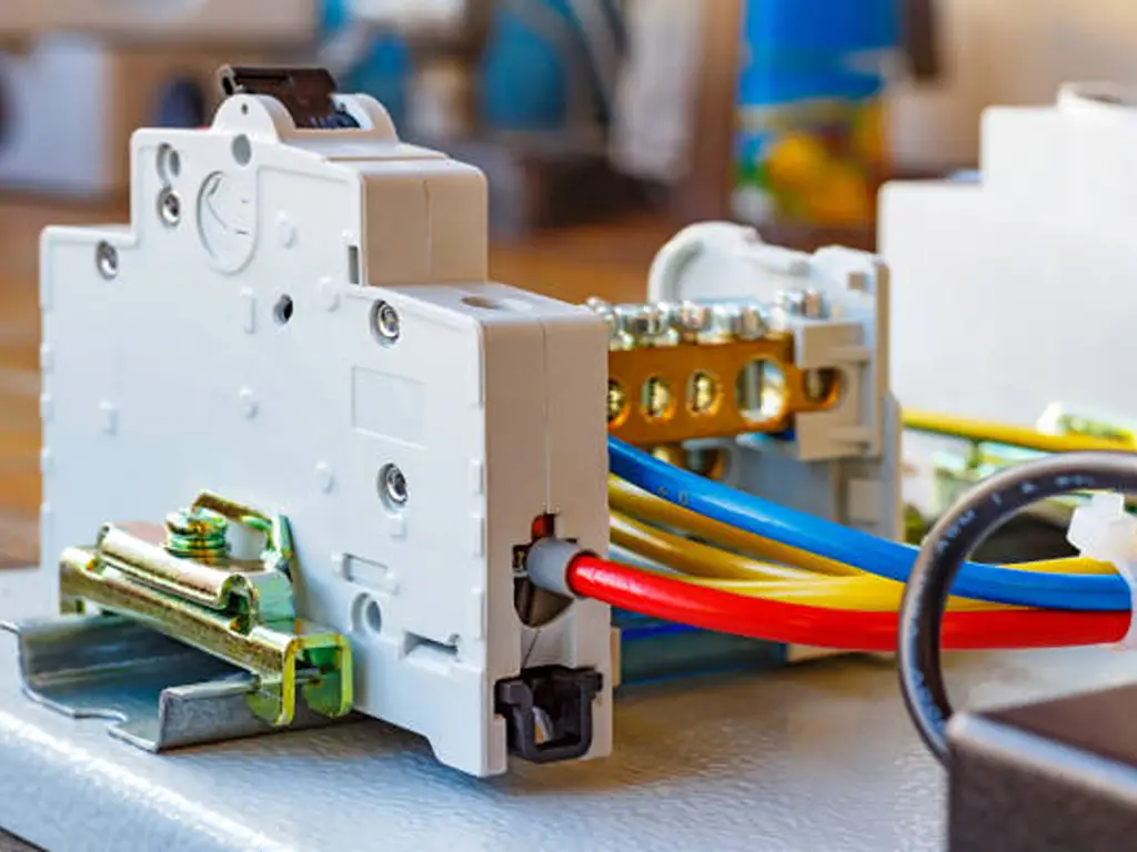
Can You Connect Power Supplies in Parallel? Why the Obvious Answer Is No
Connect the + and − terminals of two ordinary DC supplies to one load and the higher-voltage unit becomes the whole show. A switching supply regulates to a fixed voltage: unit A holds 24.0 V, unit B holds 24.2 V. Unit B cannot push against the bus unit A is already holding, so it trips into overcurrent protection, or worse, sinks current from unit A. Two regulated sources in parallel simply fight: each reads the bus, sees the wrong value, and corrects in the opposite direction.
The unit with the highest output voltage naturally delivers current up to its own limit, then drops out, leaving the system short of the current it needed (DigiKey, 2016). A mismatch of a few tens of millivolts is enough to start it, and field reports range from repeated protection trips to damaged units.
The battery analogy fails here. A drained cell sags in voltage and accepts charge from a healthier one; a switching supply actively defends its setpoint. And if you searched for series vs parallel circuit formulas, UPS paralleling, or a bench supply’s internal channel modes: those are different topics; this article is about combining DC outputs.
For most readers the useful question is not “can I” but “what is the safe way to reach my goal.” Two of the three answers below cost almost nothing.
Three Safe Ways to Combine Power Supplies in Parallel — and the One Dead End
First, separate two goals that are constantly confused. More current means the load genuinely exceeds one supply and the units share it. Redundancy means the load fits inside one unit and a second unit keeps the system alive if the first fails. The paths overlap, but the product choices differ: redundancy is where decoupling hardware earns its keep.
Dead end: direct hard-parallel. Covered above. Supplies that are built to be paralleled are legitimate; they are Path 3. An ordinary supply without declared parallel support cannot be made safe by trying harder.
Path 1 — Split the load instead of the current. When two smaller units stand in for one failed larger unit, the cheapest safe answer is often no paralleling at all: tie the negatives together for a common reference and feed one half of the load from each positive. Zero extra parts, zero circulating current, and either unit can be serviced without dropping the other half. The catch: your load must split cleanly into, say, two zones, two motors, or two banks of devices.
Path 2 — Diode-decouple the outputs. Put one power diode in each supply’s + line before the common bus, so current only flows out of a unit, never back into it. If one unit dies with a shorted output, its diode blocks the healthy unit from dumping into the fault. Use Schottky types for the lower forward drop and rate them at least 1.5× the expected voltage and current per unit. You lose roughly 0.3–0.5 V across the diodes, which is noticeable on a 5 V rail and negligible on a 24 V one. Set both supplies to nearly the same output voltage and expect an uneven split: 40:60 sharing is realistic and fine for redundancy, while a perfect 50:50 is not achievable this way (PULS, 2022). At real current the diodes run hot. Mount them on a heatsink or metal panel, not shrink-wrapped in a harness.
Path 3 — Use hardware built to share. Industrial DIN-rail catalogs divide supplies into ordinary units and units designed for parallel operation. Parallel-capable models carry a current-share feature: CS/share terminals, a droop-share link, or an explicit “parallel operation up to N units” statement. Redundancy modules sit between two or more supplies and the bus, decouple them, and add a DC-OK relay contact for monitoring; modern DIN modules use MOSFETs instead of diodes to cut heat and voltage loss (MEAN WELL’s DRDN20/40 class supports 1+1 and 1+N redundancy at 20 A or 40 A with two DC-OK contacts) (MEAN WELL, 2020). This path costs money and is engineered end to end; the next section covers how to choose it.
Choosing a Redundant Power Supply Setup: 1+1 vs N+1, and Reading the Spec for Parallel Capability
Once the goal is redundancy, two numbering schemes dominate, and they have different product requirements.
1+1 vs N+1: how many supplies, and what rating
1+1 redundancy uses two identical supplies, each able to carry the entire load alone, plus decoupling. Because no unit is ever asked to exceed its rating, 1+1 works with ordinary, non-parallel-rated supplies, as long as they are decoupled (PULS, 2022).
N+1 redundancy installs one spare beyond the number required. Because the group balances only if the units share current, N+1 requires supplies explicitly rated for parallel operation. An ordinary unit cannot fill this role (PULS, 2022). After paralleling, treat 90% of the combined rated power as the usable ceiling (MEAN WELL, n.d.).
How to tell whether a supply can be paralleled
Read the datasheet like a checklist:
- A current-share interface. CS or share terminals that wire between units (some families call them P, LP, or PLINK), or a documented droop-share function that needs no wire.
- An explicit parallel rating. “Parallel operation up to N units” with a maximum count; most manufacturers cap arrays at four to six units.
- A DC-OK / alarm contact. Without it you cannot tell the PLC that a unit dropped out.
- Silence means no. If the spec table lists hiccup-mode overload, ripple, and temperature range but never mentions paralleling, treat the unit as single-operation-only. That is the state of most slim DIN-rail supplies in the 15–480 W class: good units, one per bus.
Wiring rules matter as much as the rating. Keep the output voltage difference between units under 0.2 V, and connect the units to each other with short, large-diameter wire before running one pair of leads to the load. Also keep the total load above roughly 10% of a single unit’s rating: below that, power-good and alarm signals can misbehave even though nothing is wrong (MEAN WELL, n.d.).
| Scenario | Recommended setup | What to verify | When to switch |
|---|---|---|---|
| Permanent expansion (load exceeds one unit) | Parallel-rated units (2–4), or split the load | Same model and batch; CS terminals linked; ≤90% of combined rating; under 0.2 V difference | Drop back to one unit when the load shrinks |
| New cabinet, 1+1 redundancy spec | Parallel-rated pair, or ordinary units + redundancy module | Each unit carries the full load alone; DC-OK contact to the PLC; separate AC feeds | Verify each unit delivers full load at cabinet temperature |
| Production line, N+1 | Parallel-rated units only (must be share-capable) | N units’ rating ≥1.1× the load; keep margin per unit | Downgrade to 1+1 if cabinet space runs out |
| Temporary replacement (big unit failed, spare on order) | Split the load, or ordinary units + diode decoupling | Load must split in two, or the voltage drop must be acceptable | Revert to the single unit when the spare arrives |
Parallel-capable supply, or ordinary supply plus a redundancy module?
For a new cabinet, buy to the spec: parallel-capable supplies for N+1, and for 1+1 either a parallel-capable pair or ordinary units behind a redundancy module. For a cabinet already on the floor, the retrofit answer is almost always ordinary supplies plus a module: you keep the footprint and gain the module’s DC-OK contacts. One warning from the module makers is worth taking seriously: a supply with a parallel function is not automatically redundancy-ready, because active current-sharing circuits generally lack reverse-current protection. If a paralleled unit fails with an output short, it can drag the bus down unless something decouples it. That is exactly what the diodes or the MOSFET-based module provide (MEAN WELL, 2020). And feed each redundant supply from a separate AC source where possible, so a lost phase cannot take out both units at once (PULS, 2022).
Why Power Supplies in Parallel Fail: Sharing Failures, Light-Load Traps, and Field Checks
Every parallel-rig failure traces to one idea: current must be shared, not merely allowed. Without sharing, the highest-voltage unit carries the load until it hits its limit and shuts down. Two mechanisms fix that (DigiKey, 2016):
- Droop (passive) sharing lets output voltage sag slightly as current rises, so an overloaded unit drops its voltage and the others pick up slack. Simple and robust; the trade-off is looser regulation.
- Active sharing ties the units’ loops together through a share wire so they regulate to the same current. Tighter balance, but the extra wiring and the missing reverse protection mean it must be paired with decoupling when the goal is redundancy.
A diode or a module between each supply and the bus is what turns “parallel” into “redundant” — it blocks backfeed into a failed unit’s shorted output.
Skip the decoupling and a single failure converts your redundant pair into a system-wide outage.
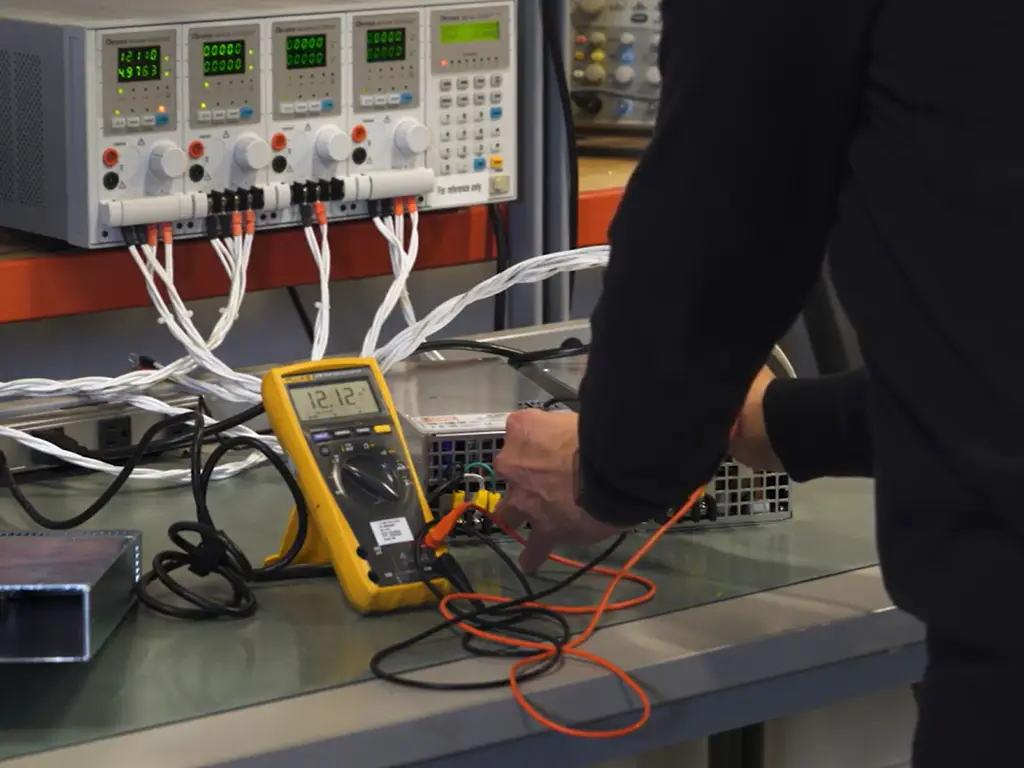
Field checks: light-load alarms, hot-swapping, and diode-rig symptoms
When a combined setup misbehaves, work the list in order:
- Isolate first. Disconnect the bus, run each supply into its own load, and verify voltage and DC-OK on each. This separates “one bad unit” from “bad combination.”
- Respect the light-load rule. Below roughly 10% of a single unit’s rating, power-good/alarm signals may not assert correctly and sharing can go lopsided; that is documented behavior, not a broken unit (MEAN WELL, n.d.). Load the bus or ignore the alarm, but know which you are doing.
- Measure a diode rig correctly. Bus voltage at no load should read about 0.3–0.5 V below the supplies’ setpoints. If it reads full setpoint, a diode is shorted and that unit is no longer isolated. Hot diodes at modest load means undersized parts or missing heatsinks, the most common DIY failure.
- Do not hot-swap unless documented. Pulling and replacing a unit on a live shared bus is safe only when the hardware is rated for it. On a diode rig, drop the load or power down the rail first.
- Never mix brands, models, or ratings in one group. Different setpoints and ripple profiles defeat sharing before you start; if the units must differ, split the load (Path 1).
If the bus voltage is unstable or protection trips repeatedly even with matched units and correct wiring, stop: the problem has moved out of the parallel arrangement and into the units or the wiring upstream.
What Parallel Power Supplies Mean When You Sell or Stock Them
When a customer asks whether two 24 V supplies “can be connected in parallel,” they rarely want a yes or no. The question usually means one of three things. The load outgrew a single unit; a unit died and two smaller ones sit on the shelf; or the machine cannot be allowed to stop. Each intent leads to a different answer, and a different order.
The volume sits in the repair-and-replacement logic. A 40 A supply fails, the spare is two weeks out, and the technician has two 20 A units. That is Path 1 (split the load) or Path 2 (diode rig) territory: both are legitimate 1+1-style arrangements while each unit can carry its half, or the whole load, respectively. So ask about the goal (capacity, replacement, or uptime) before you quote. The goal decides whether the customer needs one bigger unit, a matched pair with decoupling, or a parallel-rated pair with a redundancy module.
For a stocking strategy, this suggests pairing rather than supersizing. Instead of one large SKU per voltage band, stock matched pairs of standard supplies alongside the pieces that make them safe to combine. That means a redundancy module (or diode kit), a branch fuse or miniature breaker per supply output, and bus terminals sized for short, thick parallel wiring. A full-line distributor can ship the DIN-rail supply, the module, the branch protection, and the terminal block in one order. The honest boundary matters too. For a load comfortably inside one unit’s rating, the right advice is a single supply plus a spare, not a parallel pair. And 1+1 redundancy doubles availability, never capacity.
If you need help turning this into a bill of materials, send your spec sheets and cabinet drawings to our product selection service; we match DIN-rail supplies, redundancy modules, and protection against them. We can sample-test the combination before you commit to a batch, so send us the load figures and we will tell you which pairing is the honest one. OMCH sells the pieces and the pairing, because the pairing is where parallel power supplies actually work.
References
- DigiKey. “Properly Configure Parallel Power Supplies to Share Load Current or Risk System Failure.” 2016. https://www.digikey.com/en/articles/properly-configure-parallel-power-supplies



 English
  Arabic
  Turkish
  Russian
  Spanish
  French
  Indonesian
  Portuguese
  Thai
Thai  Vietnamese