












The machine runs, the motor spins, and the counter on the panel shows nothing. Or it counts in the wrong direction. Or the replacement encoder lets the smoke out on power-up. In all of these scenes the wires are usually innocent. The fault is an electrical-interface mismatch: the wrong output circuit, the wrong supply voltage, or an output never meant to talk to the input it was plugged into. This guide walks through incremental encoder wiring from the signals up, then shows you the five specifications that decide whether a replacement encoder wires in on the first try.
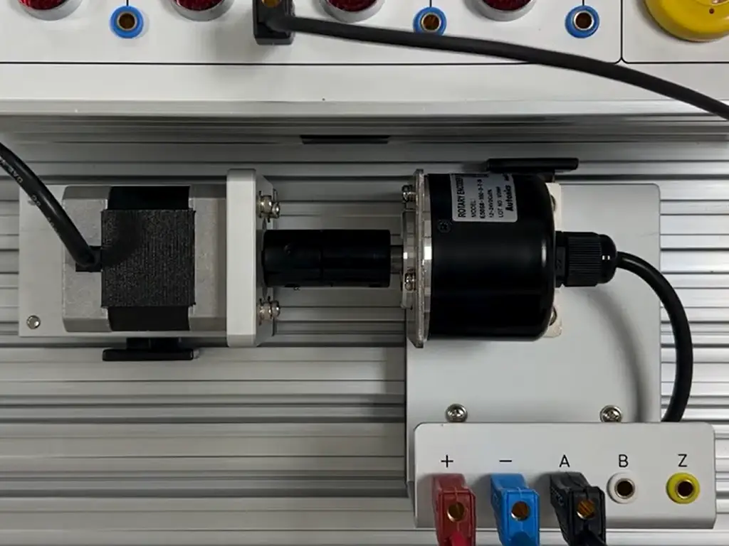
What Incremental Encoder Signals Are: A, B, and Z Wires Explained
An incremental encoder does not report a position. It emits a stream of pulses, one edge per unit of shaft movement, and the counter reconstructs speed, direction, and relative position by counting them. That is the whole difference from an absolute encoder, which remembers its position after a power loss. An incremental system must re-find its reference (usually with the Z pulse) at every power-up.
Three signals matter in incremental encoder wiring:
- Channel A and Channel B are square-wave pulse trains, offset by 90 electrical degrees of phase. Count only A and you have speed. Count A and B together (quadrature counting) and the phase relationship tells you direction: if A leads B in one rotation direction, B leads A in the other.
- Channel Z outputs one pulse per revolution. It is the index, the "this is the top of the turn" marker used for homing and for verifying that no pulses were lost.
- PPR (pulses per revolution) is the resolution. Common industrial values run from tens to over a thousand per turn. More pulses per turn means finer measurement, but also a higher output frequency at the same shaft speed.
One naming trap before we go further. The "incremental encoder" hobbyists wire to a microcontroller (the detented panel knob) is a mechanical contact switch that needs no power. The industrial encoders covered here are powered devices (5–24 V DC) that output real A/B/Z digital signals, and the wiring rules do not transfer between the two.
The Five Incremental Encoder Output Types — and How to Read Them Off the Nameplate
Every encoder maker sells what looks like the same device in several electrical variants. The mechanical platform, shaft, housing, even the resolution ladder, can be identical across variants. What changes is the output circuit, the stage inside the encoder that drives the signal wires. This is the single most important fact in incremental encoder wiring: the output circuit decides which counter input the encoder can drive, and it is normally encoded in the model suffix.
| Output circuit | What it does electrically | Typical supply | Where you meet it |
|---|---|---|---|
| Voltage output | NPN stage with a built-in series resistor (~2 kΩ); swings from high-impedance to ground | 5–12 V DC | Short cable runs into high-impedance inputs; the cheapest legacy variant |
| NPN open collector | Sinks current to ground when active; needs a sourcing input or an external pull-up resistor to your supply | 5–24 V DC | The most common repair-market encoder in machinery, the workhorse variant |
| PNP open collector | Sources current from its supply when active; needs a sinking input | 12–24 V DC | Machines wired with European-style sinking PLC inputs |
| Complementary (push-pull) | Contains both NPN and PNP stages, sinks and sources, so it drives either input type | 12–24 V DC | Preferred where one spare must suit unknown inputs; rated for longer single-ended runs |
| Line driver (RS422) | Differential outputs: A and /A, B and /B (often Z and /Z), driven by an RS422 chip | 5 V DC (±5%) | Servo drives and long, noisy cable runs; the highest-performance option |
In the incremental encoder family that dominates machine repair, the resolution list is shared across all five variants. Read the suffix and you know the output circuit and the supply voltage before you open the box.
Supply voltage: the 5 V and 12–24 V families are not interchangeable
Encoder power comes in three broad bands: 5 V DC (nearly always the RS422/line-driver family), 5–12 V, and 12–24 V DC (the dominant industrial band). Two rules matter more than any wiring diagram:
- A 12–24 V encoder must not be driven from, or connected into, a 5 V circuit, and a 5 V encoder fed from 24 V can fail instantly. Makers print this warning on the spec table; take it literally.
- The encoder's 0 V wire must tie to the same common as the counter input and the supply. A floating or double-grounded common produces the kind of intermittent counting that looks like an encoder fault.
Wire colors are not a standard — read the datasheet and the suffix
There is no universal incremental encoder color code. Each manufacturer documents its own table: one European catalog maps white, brown, green, yellow, gray, pink, blue, red, plus shield, to its 12-pin connector; an American maker's 8-pin single-ended table is different again. Two encoders with identical wire colors can be wired completely differently. If the cable is cut, the label is gone, or you are swapping brands, this is the reliable sequence:
- Read the nameplate. Output circuit and supply voltage are usually printed, or encoded in the model number.
- Decode the model suffix against the manufacturer's table (many makers publish the full decode in the datasheet or installation manual).
- Only then look up that exact model's color table or connector pinout.
Wire colors are per-datasheet, not per-industry. Two encoders with the same colors can be wired differently. Verify the model number before trusting a color.
A torn-cable case from the field makes the point: a technician with an 8-wire encoder of unknown origin posted photos asking which wire was which. The thread could only answer once the model number was identified and its data sheet pulled. The model number, not the colors, is the key.
The output circuit is the part the model suffix encodes.
The letters after the dash say which one you are holding.
Matching the Output to Your Counter Input: the Compatibility Matrix
Now the wiring decision itself. The counter side (a PLC high-speed counter card, a drive's encoder port, or a standalone counter) has an input circuit that is already fixed. Sinking or sourcing is the vocabulary you need: a sourcing input supplies current and expects the encoder to sink it (NPN open collector or voltage output). A sinking input absorbs current and expects the encoder to source it (PNP open collector). Complementary outputs drive either. Differential inputs expect paired A//A, B//B signals.
| Encoder output | Pairs with | Extra parts needed | If you force it anyway |
|---|---|---|---|
| Voltage output | High-impedance / sourcing inputs, short runs | Usually none (resistor built in) | Weak edges on long or capacitive runs, missed counts |
| NPN open collector | Sourcing inputs (PLC sink/source labels differ by maker; check the manual) | Pull-up resistor to your supply voltage if the input does not provide one (one maker's schematic documents 2.2 kΩ to +V) | No counts at all: the output cannot pull the input high |
| PNP open collector | Sinking inputs | None | No counts; possible damage if the input clamps to a lower rail |
| Complementary | Sinking or sourcing, single-ended | None | Works; this is the point of the type |
| Line driver (RS422) | Differential input (A//A, B//B) | 120 Ω termination at the receiver for long cable runs | Counts with noise; a single-ended input reads only one side of the pair |
The one-sentence rule that settles most wiring questions: the counter input is the fixed fact, and the encoder output must accommodate it. Check the counter's manual before choosing or ordering the encoder, not after. This is where manufacturers' terminology bites: one vendor calls a part "push-pull," another "complementary," a third just prints "PP" in the model number. Same electrical family, three labels. Decode the model, don't guess from the name.
Single-ended vs. differential: when one wire per channel is not enough
Single-ended wiring uses one wire per channel (A, B, optionally Z) against a common ground. It is simple, cheap, and perfectly reliable inside a clean cabinet over short runs. Differential wiring sends each channel as a twisted pair carrying complementary signals, A and /A, B and /B, and the receiver subtracts them. That rejects common-mode noise picked up along the cable. Differential is the answer when the run is long or the environment is electrically loud. Single-ended is for short runs in mostly interference-free space (motioncontroltips.com explains the single-ended vs. differential tradeoff).
Two practical notes. First, the boundary is not just "differential vs. not": a complementary (push-pull) output is still single-ended but drives strongly, so manufacturers rate it for longer runs and higher-interference environments than open collector. One maker specifies its complementary variant for runs beyond 10 m. Second, when an RS422 line driver runs a long cable, the line should be terminated at the receiver end. The common value is 120 Ω, and encoder catalogs state that RS422 long-distance operation requires this wave-impedance termination.
Shielding, grounding, and the wiring practices that prevent phantom faults
Most "intermittent encoder" faults are electrical noise, and most noise is a wiring practice problem. The rules are few:
- Run encoder cable in conduit or away from power cables. Keep at least roughly a foot of separation from motor and VFD wiring, and never share the same bundle.
- Ground the shield at one end only. Grounding both ends creates a ground loop that injects exactly the AC noise you were shielding against.
- Use twisted pairs for the signal lines where the cable construction allows.
- Watch the frequency budget: output frequency = PPR × RPM ÷ 60. A 1000-PPR encoder at 6000 r/min produces 100 kHz, the rated maximum of many encoders, leaving no headroom for cable capacitance. High resolution plus long cable is how "it worked on the bench" becomes "it drops counts on the machine."
Not sure which output circuit your counter actually accepts? Send us the counter card model — we match the encoder to its input before you order.
Match my encoderIncremental Encoder Wiring Symptoms and Fixes: No Counts, Wrong Direction, or Noise
When a freshly wired encoder misbehaves, work the symptom table before suspecting the encoder itself. Most "failed encoder" returns are interface mismatches that would repeat with any replacement.
| Symptom | Check first | Typical fix |
|---|---|---|
| No counts at all | Power present and common tied to the counter's 0 V? Output type matched to the input? | Match the circuit (add pull-up for NPN into a sourcing input), or confirm the output type against the nameplate |
| Counts one way only / wrong direction | A and B phase order | Swap the A and B wires. For differential, swap A with /A. Direction reversal on replacement is a wiring fix, not a wrong part |
| Erratic extra counts | Noise: cable near power wiring, shield grounded at both ends | Ground the shield at one end, reroute away from VFD cables, move to complementary or differential if it persists |
| Loses counts at speed | Frequency budget and cable length | Lower PPR, shorten the run, or go differential |
| Z pulse missing or unstable | Z wired to the right input and enabled in the counter? | Wire Z (and /Z if differential) and give it the same shielding care as A/B. The index channel is the one that must never glitch |
| Smoke, heat, or dead unit on power-up | Supply voltage and polarity against the nameplate | Power down immediately. A 5 V unit on 24 V, or reversed leads, are the classic causes; confirm before replacing |
Two honest boundaries. First, the table is a first-pass diagnostic. A scope (or the counter's diagnostics view) is what separates electrical noise from mechanical vibration, which looks very similar. Second, if a machine worked before a swap and misbehaves after, suspect the interface before the part. That bias alone prevents most repeat failures.
Replacing an Incremental Encoder: Five Specs to Lock Down Before You Order
Replacement is where incremental encoder wiring is actually won or lost, because the wiring decision moves from the installer to the order desk. When a customer sends an old part number, the differences that cause returns are almost never mechanical. They are electrical, and they are all knowable before the PO goes out. Every interface variable discussed above collapses into five questions:
Five questions before you order a replacement incremental encoder
- What input does the counter or drive accept: sinking, sourcing, or differential?
- What supply voltage does the machine give the encoder, and does the replacement need the same band?
- Is the PPR the same (or within the counter's frequency budget at full speed)?
- Does the machine need Z, or on a servo, U/V/W commutation channels?
- Cable and run: leads or connector, and is the run long or noise-exposed enough to demand complementary or differential output?
1. What input does the counter accept? Sinking, sourcing, or differential decides the output family: NPN for sourcing, PNP for sinking, complementary for either, line driver for differential.
2. What supply voltage does the machine provide? The replacement must sit in the same band. A 12–24 V machine will not run a 5 V part, and a 5 V input card will not tolerate a 24 V encoder.
3. Is the PPR identical? Same PPR is the safe answer. Different PPR changes speed scaling and can exceed the input's frequency limit at full speed.
4. Which channels are actually used? A/B-only machines don't need Z, but machines that home do. Servo drives additionally expect commutation (U/V/W) channels.
5. What is the cable situation? Connector or flying leads must match the machine, and long or noisy runs push the choice toward complementary or differential output.
Answer all five and the replacement is wiring-compatible by construction. The installer's job becomes mechanical. The same discipline keeps a parts business's returns low: organize stocking and quoting by electrical interface rather than brand, and one set of slots serves machines running several nameplates. The repair-market volume sits in the 12–24 V open-collector and complementary slots; 5 V differential parts are the servo and long-run tier. Five slots (5 V line driver, 12–24 V complementary, 12–24 V NPN, 12–24 V PNP, 5–12 V voltage output) mirror the five output circuits exactly.
One boundary remains: these questions cover the electrical interface only. Shaft diameter, mounting, and coupling are a separate check, and mixing the two lists is how "it fits electrically" becomes "it doesn't fit the machine."
Getting the interface right starts at the catalog, not the terminal block. Our incremental encoder range carries all five output circuits (NPN, PNP, complementary, line driver, and voltage output) across the standard 5–24 V supply bands. When a customer sends an old part number or the counter card model, our product selection engineers confirm output circuit, supply, PPR, and channel count before we quote (see the incremental encoder range). Send us the nameplate. The wiring-compatible variant is the one we ship.
Get a replacement encoder that wires straight in
Send us the old part number or the counter card model. Our engineers confirm output circuit, supply voltage, PPR, and channel count before we quote.
References
- Motion Control Tips. “FAQ: What Are Ways to Wire an Incremental Encoder into a Motion System?” https://www.motioncontroltips.com/faq-what-are-ways-to-wire-an-incremental-encoder-into-a-motion-system/
- PLCTalk Forum. “How to Wire Incremental Encoder: Accu-Coder Model-Number Decoding and Open-Collector Pull-Up Discussion.” https://www.plctalk.net/forums/threads/how-to-wire-incremental-encoder.110063/



 English
  Arabic
  Turkish
  Russian
  Spanish
  French
  Indonesian
  Portuguese
  Thai
Thai  Vietnamese