












Ask five different sources how a time delay relay works and you will get five different answers. Not because they disagree, but because most explanations blur two separate questions: how the delay is physically made, and how the relay behaves while it waits. The first is hardware history. The second decides whether your machine does the right thing at the right moment. This article covers both, then spends most of its effort on behavior, because that is where field failures, replacement mistakes, and costly returns actually come from.
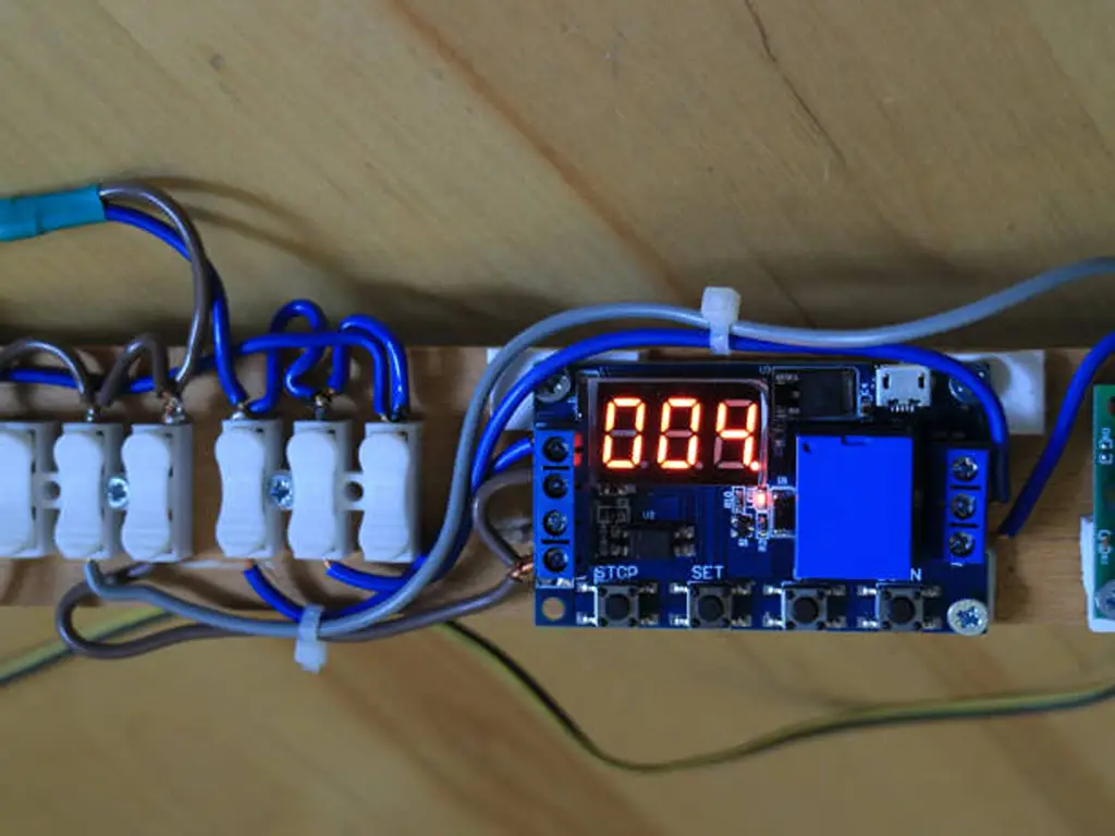
What Is a Time Delay Relay — and What Is the “Delay” Doing?
A time delay relay is a control relay with a timer inserted between its coil and its contacts. A standard relay flips its contacts the instant its coil is energized or de-energized. A time delay relay does not. Its contacts hold until a timing condition is met: a set time elapses, a trigger edge arrives, or a reset clears the cycle. Strip it to the skeleton. A control input (coil or power terminals) supplies the energy and the intent to time. A timing stage counts down the set delay. An output relay does the actual switching, usually with NO, NC, or both contacts available.
The behavior difference that matters first is the direction of the delay. On-delay (also called delay on make or delay on operate): power is applied, the timer starts, and the contacts change state only after the set time. Remove the control voltage and the cycle resets. Off-delay (delay on break or delay on release): the output stays energized while a trigger is present. Remove the trigger, and that is when the timer starts; the output drops out at time-out.
Why install one at all? Starting motors in sequence keeps them from all drawing inrush at once. Keeping a cooling fan or conveyor running after its drive stops buys time for heat to clear. Sequencing purge or pre-lubrication steps protects equipment before it fires up. Every one of those jobs is “switch something, but not quite yet,” which is what this component exists for.
One scope note: this article covers time delay relays in electrical control circuits. Pneumatic air timers that delay an air signal are a separate device family, and 12 V automotive delay modules follow the same physics in a different world. The principles below apply across all of them; the wiring details do not.
How a Delay Is Actually Made: Four Timing Mechanisms
The same “wait, then switch” behavior has been built four ways over the decades, and old machines still carry all four. Recognizing the mechanism tells you a lot about what a timer will do when things go wrong.
Pneumatic timers compress a self-contained bellows when the coil energizes; air escapes through a needle-valve orifice at a set rate, and the contacts trip when internal pressure crosses its threshold. They need no external air supply; the bellows is built in. Synchronous motor timers drive a geared motor that walks a cam to a set position. The delay is literally the cam’s travel time, so accuracy follows the grid frequency. Electronic RC timers charge a capacitor through a resistor and fire the output relay when the capacitor crosses a comparator threshold. The R × C product is the delay. Microprocessor-based timers count crystal-oscillator cycles and are the modern default. They are also the platform for multi-function models whose DIP switches select between several timing functions.
Four ways to make a delay — mechanism, accuracy, and what happens when power dies
| Mechanism | How the delay happens | Typical repeat accuracy | After power loss | Where you meet it |
|---|---|---|---|---|
| Pneumatic | Bellows air bleeds through a needle valve | ±10% of set time; a 20 s setting can trip in 18–22 s (Rockwell 100-FPTA180) | Can briefly hold its last state on stored bellows energy | Old panels, wet or harsh locations |
| Synchronous motor | Geared motor walks a cam to a set angle | Follows line frequency; no free-running drift | Stops instantly; cam parks or resets by design | Motor-timer retrofits, older HVAC |
| Electronic RC | Capacitor charges through a resistor | Repeatable; loosens with temperature | Drops out and resets almost instantly | Mid-era panels, economy timers |
| Microprocessor digital | Crystal oscillator counts cycles | ±0.1% or better is routine in supplier literature | Drops out and resets instantly unless storage circuitry is fitted | New panels, multi-function models |
Two numbers deserve respect here, and both are documented rather than marketing. Pneumatic repeat accuracy is ±10% of the set time. Rockwell’s support documentation for its 100-FPTA180 pneumatic timer states it directly: a 20 s setting can land anywhere from 18 to 22 s (Rockwell Automation Knowledgebase). SMC’s air-timer literature quotes the same ±10% repeatability (SMC Pneumatics). Microprocessor-based timers sit at ±0.1% or better per supplier literature (GEYA), two orders of magnitude tighter. If a process cannot tolerate 18–22 s out of a 20 s setting, no needle-valve adjustment will ever fix it. That is a mechanism change, not a tune-up.
The boundary cuts the other way too: pneumatic does not mean obsolete. Pneumatic timers still earn their keep. They suit places with no control power at the moment of timing, environments electronics dislike, and circuits where a brief mechanical hold after power loss is load-bearing. They are dated, not defective.
The Behavior Map: Five Timing Functions, the Contact Quadrant, and What Happens When Power Dies
The mechanism tells you how a delay is made; behavior tells you when the contacts move, the part you troubleshoot, specify, and sell. Read any timing function with three questions: what starts the timing, what does the output do when timing ends, and what resets it?
The five basic timing functions
On-delay is the most common. Control voltage applied → timing starts → output energizes at time-out; removing control voltage resets it. Classic jobs: staggering motor starts, star-delta changeover, burner purge before ignition.
Off-delay is second. Control voltage applied → the relay is armed. Apply a trigger → output energizes immediately. Remove the trigger → timing starts → output de-energizes at time-out. Re-applying the trigger mid-timing resets the count and keeps the output energized. Classic jobs: a fan that must run on after its motor stops, a door held open on a timer.
Interval on energizes the output immediately on power, times, and drops the output at time-out: a “keep this on for exactly X seconds” function. One-shot (single shot) is armed by control voltage and fires one timed pulse per trigger; triggers arriving during the pulse are ignored. Flasher / repeat cycle cycles the output at the set time(s) for as long as control power is applied: warning beacons, intermittent feeders.
Terminology is where buyers get lost. Delay on make, delay on operate, and delay on energize are all the same on-delay behavior in different vendor vocabularies. Its off-delay mirror runs through delay on break, delay on release, and delay on de-energization. And “8-pin vs 11-pin” is a socket question, not a function question. Never let package shape change the function you order. Function definitions above follow Macromatic’s timing-function reference.
The contact quadrant: NO/NC × timed-closed/timed-open
A time delay contact must be specified twice: normally open or normally closed, and whether the delay acts in the direction of closing or of opening. Cross those two axes and you get the four contact behaviors that All About Circuits lays out as NOTC, NOTO, NCTO, and NCTC:
The contact quadrant: state × direction of delay
| Code | Resting state | On energize | On de-energize | Common job |
|---|---|---|---|---|
| NOTC (NO, timed-closed) | Open | Closes after the delay | Opens immediately | The on-delay workhorse; a NO contact that makes after t |
| NOTO (NO, timed-open) | Open | Closes immediately | Opens after the delay | Off-delay output; a NO contact that breaks after t |
| NCTO (NC, timed-open) | Closed | Opens after the delay | Closes immediately | “Cut this circuit after t” jobs on energize |
| NCTC (NC, timed-closed) | Closed | Opens immediately | Closes after the delay on de-energize | Off-delay NC; re-makes after t when released |
Reading a timing diagram is the same skill in picture form: one line for the control or trigger input, one for the output contact, time flowing left to right. The whole diagram is two questions: when does the input jump, and how long after that jump does the output move? Answer those and you can predict the relay in any circuit without memorizing anything. When you pick a replacement, match the symbol on the old nameplate to this quadrant first, then to the function. Two relays with the same function code but different quadrant contacts are not interchangeable.
What actually happens when power dies
Here is the sentence most guides skip, and the one behind the most field confusion:
The default answer to a power loss is: reset
Timing only runs while its circuit stays alive. A delay that keeps running after the power dies is a special energy-storage design — not a standard feature of off-delay.
Off-delay in particular splits into two products that look identical on a shelf. Trigger-type off-delay needs control voltage present the whole time: trigger removed, timer runs, and if the supply dies mid-timing the output drops immediately. There is nothing left to count with. “True” off-delay keeps its output energized after control power is removed, timing out on stored energy, usually a capacitor rail. Macromatic’s reference describes the sequence: output energized on power, timing begins when input voltage is removed, and re-applying power during the delay resets it. The same reference notes that some units need the supply applied for about half a second first, so the storage rail can charge (Macromatic). Pneumatic and motor timers sit in a third camp, able to hold their last contact state briefly on mechanical stored energy after power dies. “These devices will be able to prevent contact state change briefly after loss of power,” as one engineer put it in a retrofit discussion (r/engineering). An electronics-based unit without storage cannot do that, and expecting it to is the classic surprise.
Behavior on interruption — what each function does when power or trigger misbehaves
| Function | Control power removed mid-timing | Trigger removed mid-timing | Trigger re-applied during timing |
|---|---|---|---|
| On-delay | Output drops; count resets to zero | No trigger input — N/A | No trigger input — N/A |
| Off-delay (trigger type) | Output drops immediately | Timing starts — this is the trigger it waits for | Count resets; output stays energized |
| True off-delay (storage type) | Timing continues on stored energy; output drops at time-out | No trigger input — N/A | Output stays energized; count resets once power is back |
| Interval on | Output drops; count resets | No trigger input — N/A | No trigger input — N/A |
| One-shot | Pulse cut short; relay rearms | Pulse continues (trigger not used during pulse) | Ignored during the pulse; rearms after |
“Resets” above means the count is discarded and restarts from zero when conditions return. A handful of exotic variants, such as some percentage and repeat-cycle functions with memory modes, behave differently, so check the specific datasheet. The field consequence is concrete. A fan-run-on circuit “fixed” with a trigger-type off-delay will drop the fan instantly when control power is switched off together with the fan. That is the exact confusion one electrician posted about after expecting an off-delay to keep timing through a total control-supply loss (r/ElectricalEngineering). If the fan must run on after power dies, you need a true off-delay unit, or a separate powered hold. Not just any off-delay.
Dead or Misbehaving? Field Checks and Retrofitting Mechanical Timers with Electronic
Field checks before you blame the timer
A timer that “stopped working” has usually lost its power, its trigger, or its setting. Work the cheap causes first:
- Measure the coil or control terminals — is rated voltage actually present when it should be? No voltage, no timing, and no relay is at fault.
- Check the trigger circuit on off-delay and one-shot types — is the trigger contact really opening and closing? A dirty limit switch or a floated PLC output starves the trigger.
- Verify the setting — knob bumped, DIP switches changed, or someone “fixed” the timing out of range.
- Time it against a stopwatch — on-delay: power on, measure to contact change. Off-delay: remove the trigger, measure to release. A pneumatic unit inside ±10% of setting is within its published tolerance, not faulty.
- Photograph the nameplate and record the function symbol before unclipping anything — the replacement gets matched to that record, not to memory.
Retrofitting pneumatic and mechanical timers with electronic relays
A quiet migration is running through maintenance shops. Old machines still run on pneumatic or motor-driven timers, and the spares have gotten expensive. In one r/engineering thread, a maintenance director quoted over US$700 for a single OEM pneumatic timer replacement. The timer sat on an orbital welding machine, and he asked why not control the same contactor with an ordinary electronic timer relay. The thread’s consensus: electronic replacement is routine and dramatically cheaper, with two caveats: wiring changes and fail-safe behavior.
The retrofit is a behavior-matching exercise, not a part-number exercise:
The replacement matrix — what to confirm before an electronic swap, and what each answer changes
| What the circuit relies on | What to confirm | Electronic answer if confirmed | If you skip it |
|---|---|---|---|
| On-delay after energize | Function is true on-delay; note the quadrant contact on the nameplate | Standard on-delay model; match NOTC or NCTO | Wrong quadrant contact inverts the logic |
| Off-delay with control power always present | Trigger type and voltage class | Trigger-type off-delay; wire the trigger correctly (dry contact vs voltage) | A voltage applied to a dry-contact trigger input can damage the relay |
| Output holds after total power loss | Does the circuit depend on the hold? | True off-delay (storage type) or a separate powered hold | The electronic default drops instantly — a behavior change, and potentially a safety issue |
| Instantaneous auxiliary contacts | Are aux contacts used elsewhere in the logic? | Model with instantaneous plus timed contacts | Missing aux means a second relay or rewiring |
| Coil or control voltage | AC or DC, and which value | Match exactly | Wrong voltage — no timing, or a burned input |
| Socket and mounting | 8-pin or 11-pin octal, DIN rail, panel | Model with the same footprint, or budget a base change | A mechanical retrofit cost surprise at the last minute |
The headline difference is row three: the power-loss hold. Pneumatic and motor timers can hold their contacts briefly on stored mechanical energy; an electronic relay without storage cannot. If the original circuit relies on that hold, a straight electronic swap changes machine behavior. Think of a fan that must cool a spindle after the stop button kills everything, or a valve that must stay put through a power dip. In safety-adjacent circuits, that is a design change, not a spare-parts purchase. One commenter in the same thread said it directly. “As long as power is present, you could exactly duplicate the behavior using electrical delay relays.” The difference only shows up after power loss (r/engineering).
The upside is just as real. Repeat accuracy moves from ±10% of setting (18–22 s on a 20 s dial) to the ±0.1% class (Rockwell Automation Knowledgebase; GEYA). And there is no needle valve to drift, no bellows to age.
When you send that replacement request, the supplier needs to answer model by model on exactly those six rows: function, power-loss behavior, trigger type, aux contacts, voltage, footprint. That is how our relay line works at OMCH: seven relay families including time-delay types, and every selection is matched by model, with the datasheet sent over before you commit. Scan our relay range and ask us with your nameplate data; we answer against the datasheet, not against guesswork.
What to Specify: Function, Voltage, Trigger, and Mounting
Ordering from scratch rather than swapping from stock? A six-line spec sheet gets a correct quote the first time. Every blank line is an invitation for the supplier to guess:
The six-line spec sheet for a time delay relay
| Parameter | Why it decides behavior | How to state it |
|---|---|---|
| Timing function | It fixes the trigger, output, and reset rules | State the function and the quadrant contact you need — e.g., “on-delay, NO timed-closed” |
| Control voltage | AC and DC circuits are different products | State it exactly — “AC 220 V” or “DC 24 V”, not “whatever” |
| Trigger type | Dry contact and voltage trigger are different input circuits | Specify a dry-contact input unless the model is marked “power trigger” |
| Time range and setting method | Fixed, knob, or DIP decides how it is adjusted in service | State the range needed, not just one value |
| Mounting and pinout | 8-pin and 11-pin octal sockets, DIN rail, panel | Match the existing base or budget a base change |
| Repeat accuracy | It sets how much the process must tolerate | ±0.1% class for tight processes; ±10% class only if you genuinely do not care |
The trigger row is where relays actually get damaged in the field, so it earns its own warning:
A relay designed for a dry-contact trigger can be damaged if voltage is applied to its trigger terminals. Only models explicitly rated as “power trigger” may see voltage there. If your control signal is a live voltage rather than a contact, say so in the inquiry.
Multi-function DIP-switch models justify their premium in one sentence. A single model that switches between on-delay, off-delay, interval, and one-shot replaces four part numbers in your drawer. Set the code, set the time, done.
Turn your six lines into the right model
Send us your spec sheet — function, voltage, trigger, range, base, accuracy — and we’ll come back with the matching model and its datasheet, so the relay is confirmed before you order.
Send my relay specThe Reseller Angle: What to Stock and What to Ask on Every Replacement Quote
If you sell these components rather than maintain them, everything above condenses into one operating rule: you are selling behavior, not hardware. Every replacement inquiry is a behavior question wearing a part-number costume.
Make the four questions automatic.
Four questions before any replacement quote
Which function — on-delay or off-delay?
Each answers to a different trigger; the wrong match inverts the logic.
Does the output need to hold after power dies?
Only a true-off-delay or storage type keeps timing through a power loss.
What control voltage?
AC and DC are different products, and so are the voltage classes.
What base — 8-pin, 11-pin, or DIN?
The base decides whether this is a swap or a rewiring job.
Question two is what separates you from a price-lister. The two off-delay designs behave differently when the power dies, so an off-delay answer without a power-loss answer is not yet a saleable order. The wrong one comes back as a return, or worse, as a machine that misbehaves in a safety-relevant way.
The retrofit current is your most reliable demand signal. Every shop still running pneumatic or motor-driven timers on old equipment is a replacement inquiry waiting to happen. OEM spares are expensive, and the behavior gap is exactly what your four questions resolve. When you quote that swap, the precision upgrade (from ±10% of setting to the ±0.1% class) and the removal of needle-valve maintenance are legitimate upsell facts, not padding. They follow directly from the mechanism differences covered earlier.
Stocking follows the same logic. An electronic on-delay, an electronic off-delay, and one multi-function DIP model between them cover the overwhelming majority of repair-market requests. The multi-function unit shrinks four drawer slots into one SKU. Keep the drawer sorted by behavior (function and power-loss handling) rather than by brand heritage or “pneumatic vs electronic” labels. The label is history; the behavior is the product.
Stock the time delay relays your customers actually ask for
Seven relay families — time-delay included — every replacement matched by model with its datasheet sent before you order, across a range you can consolidate with one supplier.
Talk to OMCH about relay supplyReferences
- SMC Pneumatics. “Air Timers / Timed Delay Relays.” https://www.smcpneumatics.com/airtimer.html
- All About Circuits. “Time-Delay Relays, Digital Textbook Chapter 5.” https://www.allaboutcircuits.com/textbook/digital/chpt-5/time-delay-relays/
- ForumAutomation. “PLC Mechanical Timing Relays.” https://forumautomation.com/t/plc-mechanical-timing-relays/3220
- r/engineering. “Pneumatic Timer Contactors vs. Timer Relays Controlling Contactors.” 2018. https://www.reddit.com/r/engineering/comments/9tkbzg/pneumatic_timer_contactors_vs_timer_relays/
- r/ElectricalEngineering. “Question About Off-Delay Timer Operation After Total Control Supply Loss.” 2026. https://www.reddit.com/r/ElectricalEngineering/comments/1v3mojz/question_about_offdelay_timer_operation_after/



 English
  Arabic
  Turkish
  Russian
  Spanish
  French
  Indonesian
  Portuguese
  Thai
Thai  Vietnamese