












A relay case carries two voltages: “24 VDC” and “250 VAC 10 A.” The first feeds the relay; the second is what it switches. Mixing them up is the most common relay mistake in the field, and it ends in a burned coil, a relay that never pulls in, or an order sent back. This guide covers what relay coil voltage is, how to read it on a datasheet, how to check a relay that misbehaves, and what the coil-voltage spectrum means if you stock relays in volume.
Relay Coil Voltage: What the Number on the Case Really Means
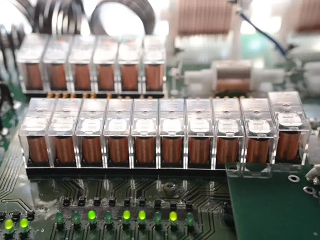
A relay is a magnetically operated switch. Pass current through the coil inside and it becomes an electromagnet that pulls the contact arm shut; stop the current and a spring returns it. Hence the two voltages:
- Relay coil voltage is the voltage applied across the coil terminals to energize the magnet. It is the relay’s “food”: feed it wrong and it refuses to work, or worse.
- Contact rating is the voltage and current the contacts can safely switch once the coil has pulled in. A “250 VAC 10 A” marking has nothing to do with the coil.
So a relay printed with both markings wants 24 volts DC on its coil and can then switch a 250 VAC, 10 A load through its contacts. The 24 V never touches the load; the 250 V never touches the coil.
Coil voltage (feeds the magnet)
Typical values: 5, 12, 24, 48 VDC; 24, 110, 120, 220-240 VAC
Contact rating (switches the load)
Typical values: 250 VAC 10 A, 30 VDC 5 A. “Which one do I need?” is a coil question, not a contact question
Two facts before you go further. Coils come in voltage versions: the same base model ships with a 24 VDC coil, a 12 VDC coil, a 220 VAC coil, and so on. You buy the version whose coil matches the voltage you can actually supply. And the same concept exists in contactors, a sibling component, but this guide stays with relays.
How to Read a Coil Voltage Specification
A relay datasheet lists up to four coil voltages, and they answer different questions:
| Specification | What it guarantees | Example (12 VDC coil) |
|---|---|---|
| Rated (nominal) coil voltage | The design reference the coil is built for | 12 VDC |
| Must-operate voltage (max) | Above this, the relay must pull in | 9 V max (75 % of rated) |
| Must-release voltage (min) | Below this, the relay must drop out | 1.2 V min (10 % of rated) |
| Max. allowable coil voltage | Above this, continuous operation risks overheating | Datasheet-specific, temperature-dependent |
The gap between rows two and three is the key: between must-release and must-operate lies an indeterminate band where the relay may hold or may switch, so you cannot rely on either. In the example above that band runs from 1.2 V to 9 V, which means reliable operation lives above 9 V, not at “anything below 12.”
The 75 % rule
75 %
of rated voltage: the typical must-operate point for DC relay coils (9 V on a 12 V coil, about 18 V on a 24 V coil)
Below it, the manufacturer guarantees nothing: in practice the relay chatters or never pulls in.
That 75 % figure is the most useful number in this article. A “24 VDC” coil is guaranteed to pull in from roughly 18–19 V upward (datasheets vary between 70 % and 80 %), with a practical ceiling near 26 V before sustained overvoltage cooks the coil. Below about 18 V, all bets are off. (AC coils often list a higher must-release; 20 % of rated is common.)
Two field techniques are worth carrying. First, read the model number. Manufacturers encode coil voltage into the part number, often as the suffix of a base model, so match the suffix, not just the base model, when ordering a replacement. Second, reverse-engineer from coil resistance with V = √(P × R), where small-to-mid general-purpose coils typically draw 0.45–0.9 W (power relays up to ~1.9 W). Measure R, solve, round to the nearest standard coil voltage, and the field narrows to one or two candidates; then confirm with the manufacturer.
Relay Coil Voltage Faults: Bench Checks That Find the Cause
When a relay “stops working,” the coil is the first suspect, and often innocent. Two minutes of bench checks separate a dead coil from a wrong voltage:
| Symptom | Likely cause | Check |
|---|---|---|
| Voltage present, above must-operate, no pull-in | Coil open circuit, or driver not sinking current | Measure coil resistance; infinite means open. Compare with a known-good coil |
| Chatters or buzzes | Supply in or below the must-operate zone; AC applied to a DC coil | Measure voltage at the coil terminals under load, not at the supply |
| Runs hot continuously | Overvoltage, sustained near or above the max. allowable voltage | Compare measured voltage with the datasheet max. line, derate for cabinet temperature |
| Died after a voltage change | Wrong supply type or voltage applied during the change | Recheck what actually feeds the coil, including the driver output |
| AC coil hums loudly | Undervoltage, or a damaged shading ring | Measure AC voltage at the coil; 80 % of rated is the practical AC floor |
The classic story deserves its own warning: applying AC power to a DC coil. A DC coil’s current is limited only by resistance; on 50/60 Hz AC the flux collapses to zero twice per cycle, so the armature chatters while the alternating current drives the coil past its thermal design. The usual ending is a few seconds of buzzing, then a dead coil. The reverse is worse in a different way: DC onto an AC coil removes the inductance that limits its current, and current climbs until the coil burns. “24 VAC” and “24 VDC” are not interchangeable, even though the numbers look the same.
One distinction prevents false diagnoses: contacts that do not conduct are not necessarily a coil problem. If you can hear the armature pull in, the coil is fine. Check the coil first, then the contacts.
Which Coil Voltage to Use: Start With Who Feeds the Coil
The coil question is never “which voltage is best?” It is “who feeds this coil?” The coil voltage must equal the control supply you actually have, so measure the supply first, then choose the coil, never the reverse.
The coil only knows one question: who feeds it?
24 VDC coil
fed by a controller output (PLC, timer, temperature controller)
Resistance-limited current with a constant draw; needs a flyback diode across it or the driver.
AC coil at the line voltage
fed directly by line power, 110/120 or 220–240 VAC by region
Inductance limits the current; shading ring stops hum; pull-in draws several times the holding current.
Universal 24–240 V AC/DC coil
accepts AC or DC across a wide band via an internal rectifier
One SKU covers the line-voltage world, but it costs more, runs warmer, and covers nothing below 24 V.
SSR input
fed by a control signal; no coil at all
Semiconductor output instead of contacts; input limits are tighter than a coil’s.
24 VDC: the control-panel standard
Modern PLC cabinets run nearly every relay on 24 VDC: it is a safety extra-low voltage, it does not induce noise into nearby analog signals the way line-voltage AC wiring can, and it matches PLC and sensor outputs directly. A DC coil is electrically simple; current is set by resistance, drawing constant, predictable wattage. It also needs a flyback diode across it (or the driver) to absorb the 100–200 V inductive spike it throws back when switched off. The spike is normal; the damage happens when no diode catches it. The small 5 V and 12 V coils belong to the same world, fed by onboard supplies: same physics, same 75 % rule.
AC line-voltage coils: the direct-switch world
AC coils are built differently because AC behaves differently. Inductance, not resistance, limits the current; the flux passes through zero 100 or 120 times a second, so AC coils carry a shading ring that keeps residual flux and stops the armature buzzing at line frequency. Pull-in draws several times the holding current, then settles once the armature closes. In exchange, an AC coil needs no DC supply, no diode, no controller. Line voltage switches it directly, which is why 110/120 VAC coils (North America) and 220–240 VAC coils (Europe, Asia, most of the world) still dominate simple machines, pumps and legacy equipment.
Undervoltage is sneakier on AC: a 220 VAC coil fed from a 208 V circuit sits near its 80 % floor, which means marginal pull-in and extra heat. If your site voltage is soft, measure it before blaming the relay.
Universal and solid-state inputs: the modern ends of the spectrum
Two options are growing at the edges. Universal coils, typically marked “24–240 V AC/DC”, contain a small internal rectifier and accept almost any control voltage in a wide band, AC or DC. One part number covers the whole line-voltage world, which is why distributors are starting to love them and technicians are starting to ask how they work. The trade-offs: they cost more, they self-heat more (the internal electronics are always powered), and they do not cover the low-voltage DC side below about 24 V. They compress voltage-variant stock; they do not eliminate it.
SSR inputs are the other end: no coil, no moving parts, just an input circuit (commonly 3–32 VDC or 24–280 VAC) driving a semiconductor output. That is often the cleaner answer for a PLC switching a heavy load, but the input requirements are tighter, so it is a different selection discipline.
Cabinet temperature is the hidden variable. Copper resistance rises as the coil warms, current falls for the same applied voltage, and the margin above must-operate shrinks. A relay that pulls in at 20 °C may sit and buzz at 60 °C in a closed cabinet on a marginal supply. The fix is a solid supply voltage and cabinet ventilation, not a “beefier” relay.
Coil Voltage by Application: A Field Matrix
The matrix below is the practical output of everything above: a per-scenario checklist you can hold next to a real order.
| Application | Coil-side choice | Parameters to verify | Where it fails |
|---|---|---|---|
| PLC or controller cabinet | 24 VDC coil matching the controller output | Must-operate ≤ 75 %; supply measured at the coil under load; flyback diode fitted | 24 V rail sags below ~18-19 V; no flyback diode kills the driver |
| Direct line-voltage switching | AC coil at the local line voltage (110-120 or 220-240 VAC) | Line voltage measured on site; AC must-release (often 20 %); no hum from the shading ring | Soft site voltage near 80 % of rated; DC applied to an AC coil equals overcurrent |
| Legacy machine replacement | Replace with the SAME coil voltage as the original | Read the old relay’s coil marking or model suffix before buying | “Upgrading” the coil voltage without checking the circuit, which still supplies the old voltage |
| Export / multi-region equipment | Coil voltage per destination region (110-120 VAC North America, 220-240 VAC elsewhere, 24 VDC in panels) | Confirm the destination region; a universal 24-240 V AC/DC variant covers mixed fleets | Stocking one line voltage and shipping to the wrong region |
| Unknown relay on the bench | Reverse-engineer before powering (resistance method) | Coil resistance; assumed power 0.45-0.9 W; round to a standard voltage | Guessing the rated voltage: measure, then match |
Three fields to confirm before every order: coil voltage and supply type, separately, because “24 V” is not complete and 24 VAC and 24 VDC coils fail differently; contact rating, separately from the coil, because the load decides one and the supply the other; and ambient temperature margin, because in a hot cabinet the supply must still clear must-operate with the coil hot.
Most replacement mistakes trace to ordering the base model without reading the coil version of the part being replaced. Read the old part first.
The replacement coil voltage equals the original’s.
The Business Side: Stocking the Coil-Voltage Spectrum
Everything above has a buying side, and for distributors it is the whole game: a relay is not one product but a family of coil-voltage versions under one base model. The customer who calls about a relay will name a coil voltage within the first sentence. That is when the spectrum stops being a spec-sheet concept.
The minimum quotable unit is “model + coil voltage”
Quoting a base model without the coil version is quoting nothing. The customer’s circuit already decided the answer, and a wrong coil voltage means a return, a re-shipment, and a customer who checks the next catalog first. Two habits close the loop: make coil voltage and supply type (AC or DC) mandatory fields on your quotation forms, and teach whoever answers the phone to ask for the coil version when a customer reads out a model number.
Two parallel volume lines, and what universal coils change
Viewed as a stockist, the spectrum has two volume lines. The 24 VDC line is the consumable of the PLC/DCS world; every cabinet rebuild and panel retrofit eats them. The line-voltage AC line (110/120 VAC in North America, 220–240 VAC elsewhere) is the consumable of directly switched machines and a vast, still-serviced installed base. Stocking only 24 VDC quietly surrenders every line-voltage inquiry to whoever stocks both. A universal 24–240 V AC/DC coil compresses the AC side: one SKU replaces most slow-moving line-voltage variants, but it does not replace the DC side, because below about 24 V there is no universal option. The practical shelf: 24 VDC in depth, a small universal range for the line-voltage world, and 5/12 VDC variants where your customers build electronics. Measure stock by spectrum coverage, not model count: ten models in one voltage band answer one kind of inquiry; five models across the spectrum answer most of them.
When qualifying a relay supplier, add the coil-voltage dimension to the checklist: which coil voltage versions does each relay family come in, how is the coil voltage encoded in the model number, and can you get a specification sheet per coil version, not just per family? OMCH’s relay family pages list the families we carry, and our product-selection service exists exactly for this: send us the model number and the coil voltage your circuit needs, and we confirm the matching version and its datasheet before you commit, so the 75 % rule, the suffix, and the voltage band are settled on paper, not discovered after the relay arrives.
If you are replacing relays in a panel or stocking them for customers who are, get in touch. We will help you match coil voltages across the relay families we stock, one model number at a time.
Send Us the Model Number and the Coil Voltage
We confirm the matching relay version and its datasheet across the families we stock, before you commit.
Confirm my coil voltageReferences
- DigiKey Forum. “Understanding Relay Coil Voltage Specifications.” 2017. https://forum.digikey.com/t/understanding-relay-coil-voltage-specifications/946
- Reddit r/PLC. “What Happens When AC Power Is Applied to the DC Coil of a Relay?” 2024. https://www.reddit.com/r/PLC/comments/1ew2m16/what_happens_when_ac_power_is_applied_to_the_dc/
- Reddit r/AskElectronics. “For a Small Power Relay, Does Reducing Coil Voltage Affect Operation?” 2026. https://www.reddit.com/r/AskElectronics/comments/1v8xixd/for_a_small_power_relay_does_reducing_coil/



 English
  Arabic
  Turkish
  Russian
  Spanish
  French
  Indonesian
  Portuguese
  Thai
Thai  Vietnamese