












A solid state relay fails on a different physics than the mechanical relay it replaced. Test it with mechanical-relay habits and it will mislead you. Its semiconductor output leaks current when off, can look dead to one multimeter and fine to another, and fails most often in the direction you least expect. This guide covers the field diagnostic sequence: symptom patterns traced to the internal structure behind them, the circuit conditions where the relay is innocent, and a replacement spec you can defend.
Is It the SSR? A Three-Check Diagnosis Before You Replace Anything
Run three checks in order. Each one eliminates a class of misdiagnosis.
Check 1. Is the control signal actually arriving? Measure the input terminals while the controller commands “on.” DC-input SSRs commonly accept roughly 3–32 V DC, and AC-input types roughly 90–280 V AC; the exact window is printed on the label. Input voltage present but no switching means the SSR is a suspect. Voltage missing means the fault is upstream: the controller output, the wiring, or a loose terminal.
Check 2. Measure load current, not just voltage. The most common field misdiagnosis in SSR circuits is a voltage reading. An SSR in the off state still passes a small leakage current (structural, not a defect), and with an open-circuit or high-impedance load, that leakage floats the output terminal to near full line voltage (ghost voltage). A clamp meter tells the truth: current near zero when off, near load rating when on. Use a LoZ (low-impedance) meter mode when available, because it loads the circuit and exposes ghost voltages. A 60–100 W incandescent test lamp works too.
Check 3. Expect the failure direction you are not expecting. Here is the counterintuitive part, and this guide will return to it: when an SSR fails, it usually fails closed. The output stays on. A relay that will not turn on is more often a circuit problem or an input problem than a dead output. A relay that will not turn off is frequently the relay.
Field sequence
Confirm input voltage at the terminals, per label range.
Compare load current, near zero when off and near rating when on, and ignore floating voltage readings.
Suspect the SSR when it fails closed, suspect the circuit when it fails open.
One warning before you open the panel:
SSR Symptoms Decoded: What Each One Means and What to Check First
Every SSR fault shows up as one of a handful of repeating patterns. Match yours, run the first-check column, and the table points to the internal structure that explains it.
SSR symptom quick-reference
| Symptom | Check first | Root cause is in |
|---|---|---|
| Input present but relay won’t turn on (LED off or dim) | Verify input polarity and voltage range on the label; verify the driver can supply enough current | Section: input structure |
| Input removed but load stays on | Disconnect the load and re-test: output still conducting means the output device failed shorted | Section: output structure |
| Intermittent or erratic switching | Check for induced noise on long input wires; check switching timing against the load | Section: switching structure |
| Output terminal reads “live” when off | Re-measure with LoZ mode or a test lamp before condemning the relay; likely ghost voltage | Section: output structure |
| Case hot to the touch, or burned smell | Measure actual load current vs. rating; inspect heatsink, thermal compound, ambient | Section: thermal structure |
| Same position burns out repeatedly | Examine the load type and its inrush; check for missing overcurrent protection | Section: switching structure + load boundaries |
Two of these patterns, “won’t turn off” and “live output,” are where working SSRs get replaced for free, because both are judged from voltage readings that semiconductor leakage makes unreliable.
Why SSRs Fail the Way They Do: Four Internal Structures Behind the Symptoms
Four structures inside every SSR (input, output, switching, thermal) each explain one family of symptoms. See the mechanism, and diagnosis stops being guesswork.
The input stage: why “no response” is usually a measurement problem
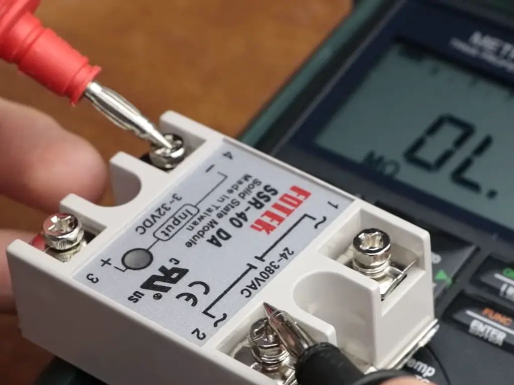
The input is an LED behind a constant-current limiter, typically holding current to about 20 mA regardless of input voltage (control.com). That design gives one input a wide voltage window, and it changes how you test it: in diode-test mode, a DC-input SSR should read roughly 1.2–2.0 V forward across the input. Two traps follow.
- “OL” does not mean the relay is dead. Many meters cannot raise their diode-test voltage enough to light the LED, and AC-input SSRs (or DC inputs above roughly 5 V) cannot be diode-tested at all. The same relay reads differently on different meters. The reading is meter-dependent, not relay truth.
- Inputs are polarity-sensitive and fragile. Reverse polarity or an over-voltage spike on the input is the classic DIY-layer killer. Confirm polarity at the terminals before suspecting the relay.
The output stage: why SSRs fail closed, leak, and lie to your meter
The output is a semiconductor switch (a TRIAC or back-to-back SCR pair for AC loads, MOSFETs for DC) with no mechanical contacts. Three consequences drive most real-world confusion.
You cannot test it like a contact. A mechanical relay is judged by resistance. A semiconductor’s resistance depends on the voltage and current the meter applies, so passive readings are only suggestive. The definitive test is at real operating conditions: energize the input and observe the output under load.
When it fails, it usually fails shorted. The engineering textbooks are unambiguous: solid-state relays have a tendency to fail shorted on their outputs, while electromechanical contacts tend to fail open (All About Circuits). A failed SSR is far more likely to leave its load permanently powered than to drop it.
It leaks, and the leakage reads like a lie. Off-state leakage is small (harmless for most loads, measurable by instruments) and it is unique to solid state: electromechanical contacts give a pure mechanical disconnect with no leakage current (Texas Instruments, Basics of Solid-State Relays, 2024). Multiply that leakage by an open-circuit load and the output floats to near line voltage. That is the ghost-voltage reading from Check 2. The relay is fine. The circuit is open. The meter is fooled.
The failure direction
A failed SSR usually fails closed.
The output stays on, not off.
Diagnose accordingly, and design safety circuits as if it will happen — because it will.
The switching stage: zero-cross vs random-on
Thyristor outputs hold conduction until load current falls below a holding threshold, so an AC-output SSR opens the circuit near the current zero rather than mid-cycle, sparing inductive loads the interruption spikes that mechanical contacts produce (All About Circuits). Zero-cross turn-on relays extend that discipline to closing: they fire at the voltage zero, so a resistive load sees minimal switching surge. Random-on (instantaneous) relays fire on demand. You need them for phase-angle control, or when switching must be immediate.
Misapplying the two is a hidden killer. Firing at an unfavorable point of the waveform, or driving a load whose inrush exceeds the relay’s surge rating, stresses the output die and eventually ends as a shorted output. When the same position fails repeatedly, check the switching type against the load before you check the relay.
The thermal stage: the derating math behind “overheating”
An SSR in conduction carries a forward voltage drop. About a volt at rated current is typical for AC-output types (check the datasheet value), and DC-output types drop less. Drop times current is heat, generated every cycle, with no contacts resting open to cool down, and it must leave through the base plate, the thermal interface, and the heatsink. Published derating shows the stakes: one manufacturer’s example rates a unit at 25 A on a 25 °C base plate, but only about 15 A on a 60 °C base plate. A load that was fine in winter can exceed its rating by summer, with no component changed.
So when a case runs hot, measure the real current (not the nameplate), then check all four links of the thermal chain: base plate to interface material, interface to heatsink, heatsink to air, and ambient temperature. Buying a bigger SSR is often the wrong fix for a broken thermal chain.
Suspect the relay but not sure what killed it? Send us the label specs and the load type — we’ll flag the mismatch before you order a replacement.
Send us your relay specsWhen the Rules Change: Loads, Safety and Environment
The four structures explain most failures. This section covers the exceptions: the loads, safety requirements, and environments where the normal rules stop applying.
Load types: what each one demands from the SSR
Not all loads are equal to an SSR, and the differences show up as field failures:
Load type boundaries for SSR selection
| Load type | Typical examples | What it demands from the SSR | Failure boundary to check |
|---|---|---|---|
| Resistive heating | Heaters, ovens, molding machines | Modest inrush; zero-cross type fine; steady current near rating | Open-circuit elements create ghost voltages that mimic SSR failure; thermal cycling ages the die |
| Incandescent / halogen lamps | Lighting banks, signage | Cold-filament inrush far above steady current | Check the relay’s stated surge rating, not just steady current: under-rated units fail shorted |
| Motors and inductive loads | Fans, pumps | Starting current several times running current; spikes on switching | Oversize for starting current; confirm snubber/MOV treatment for back-EMF |
| Solenoid and contactor coils | Valves, magnetic starters | Small steady current; inductive kickback; leakage can hold the coil in | A coil that “won’t drop out” may be held by leakage; add a bleeder or switch to an EMR |
| Switch-mode / capacitive loads | LED drivers, VFDs, power supplies | High charging inrush in the first cycles | Verify inrush against the relay’s surge rating; consider soft-start where available |
| DC loads | DC heaters, DC motors, solenoids | DC-output SSR (MOSFET); polarity discipline | An AC SSR on a DC load never turns off: DC has no current zero for a TRIAC to drop out at |
| Three-phase heating | Industrial ovens, dryers | Often two SSRs plus one permanently connected leg, by design | A “live terminal with SSR off” can be correct wiring; map the circuit before condemning the relay |
Safety boundaries: a relay that fails closed can’t protect anyone
Because failure defaults to closed, an SSR is an actuator, never a safety device. Three practices make that survivable. First, anything that must fail safe (heaters that can over-temperature, drives that must stop) needs an electromechanical relay or contactor in series, so a deliberate stop or control-power loss gives a true mechanical disconnect. Working engineers give the same advice for the same reason: SSRs more often fail closed, so anticipate it (electronics.stackexchange). Second, protect the SSR with a fast semiconductor fuse on the output. Under the IEC 60269 classification, aR-class fuses protect semiconductors against short circuit, and gR-class also cover overload. Ordinary fuses are too slow to save a shorted die, which is why SSR makers specify fast-acting protection (Littelfuse). Third, where a stuck-on output can run a process away, add independent temperature or level monitoring that cuts a series device. Never rely on the SSR to disconnect itself.
Environment and wear: do solid state relays wear out?
They have no moving parts, so they do not wear the way contacts do. But they are not immortal. Texas Instruments catalogs the real degradation paths: the internal LED’s light output decays under sustained over-temperature or over-current, and isolation insulation degrades over time (Texas Instruments, Basics of Solid-State Relays, 2024). In practice, an SSR’s life is set by its thermal history (how hot the die has run, and for how long), not by a cycle counter. Derate for ambient temperature and keep the enclosure clean and ventilated, and an SSR will outlive the machine’s contactors. Run it at the edge of its derating curve in a hot cabinet, and it will die young, predictably.
Choosing the Replacement: Read the Old Label, Recalculate the Load
When the diagnosis is done and the SSR is genuinely dead, order the replacement by copying the parameters, then re-checking the three that cannot be copied.
Copy these five from the old label. Every SSR label carries them, and they are the whole spec: (1) input voltage range and type (DC or AC input); (2) output type, AC (TRIAC/SCR) or DC (MOSFET); (3) output load voltage rating; (4) output current rating; (5) mounting and form factor (panel-mount “hockey puck,” DIN rail, or PCB).
Then recalculate, and do not copy, these three:
- Load current. The old rating was chosen for a load that may have changed. Measure the actual running current. For resistive loads, industry practice leaves a margin above continuous current (roughly 1.2–1.5× is common), and surge-prone loads should be checked against the relay’s surge rating, per the load table above.
- Load type. If anyone modified the circuit since install (a motor added to a heater circuit, incandescent lamps swapped for LED drivers), the old relay’s rating assumptions are void.
- Switching type. Zero-cross for resistive loads, random-on when you need immediate or phase-controlled switching. Buying “the same part number” preserves a mistake if the original choice was wrong.
And do not copy at all when the old relay was the victim. If this is the third failure in the same position, fix the thermal chain, the load surge, or the missing protection fuse first, then fit the replacement.
Ordering checklist
Copy the five label parameters (input type/range, output AC or DC, load voltage, load current, mounting).
Measure the real load current before trusting the old rating.
Re-confirm load type and switching type if the circuit was modified.
Order the output-side semiconductor fuse at the same time.
Stocking and Selling SSR Replacements: What the Failure Patterns Tell Distributors
For anyone who stocks or supplies SSR replacements, these patterns are a purchasing map, not just repair notes. Because a failed SSR fails closed, the repair market’s demand is permanent. Every stuck-on output and dead heater ends in a replacement order, and the buyer’s first question is almost never about brand. It is “what do I need to match?” The five label parameters above are the real stock-keeping dimensions: input type and range, output type, current class, mounting. A parameter-organized shelf beats a brand-organized one in this market. And because the root causes live outside the relay (thermal chain, load surge, missing protection), the supplier who asks “what load is it on, and what is it fused with?” sells a circuit solution, not a single component.
If you would rather not spec a replacement from memory, send us the old relay’s label and your load details. OMCH’s spec-based product selection support matches components from specifications and drawings across our 30+ category catalog of 3,000+ standard models, and our engineers confirm the datasheet before you commit. Every solid-state relay we ship carries a one-year warranty, and technical support answers around the clock for the fault that never quite fits the textbook.
Stock the Replacement Spec, Not Just the Part Number — Distributor Terms for SSRs & Protection
JGX solid-state relays sit inside our seven-family relay range, and we pair a replacement with the fuse or contactor for the same circuit — spec sheets on request, cross-reference help and application support when a customer hands you a dead relay.
Request distributor pricingReferences
- Texas Instruments (Jose Rojo). “Basics of Solid-State Relays.” July 2024. https://www.ti.com/lit/pdf/slvafu8
- All About Circuits, Lessons in Electric Circuits — “Solid-state Relays.” https://www.allaboutcircuits.com/textbook/digital/chpt-5/solid-state-relays/
- control.com Technical Articles. “Troubleshooting Solid State Relays.” 2020. https://control.com/technical-articles/troubleshooting-solid-state-relays/
- Fluke. “Dual Impedance Digital Multimeters.” https://www.fluke.com/en-gb/learn/blog/digital-multimeters/dual-impedance-digital-multimeters
- electronics.stackexchange. “Protecting against a SSR failing closed.” 2019. https://electronics.stackexchange.com/questions/417585/protecting-against-a-ssr-failing-closed



 English
  Arabic
  Turkish
  Russian
  Spanish
  French
  Indonesian
  Portuguese
  Thai
Thai  Vietnamese