












Estás creando un panel de control. Necesitas saber qué hay en su interior: no solo una lista de nombres, sino qué hace realmente cada componente, cómo encajan entre sí y qué hay que tener en cuenta a la hora de elegir uno en lugar de otro. Si estás adquiriendo estas piezas para un negocio de distribución, esa misma información determina qué productos debes tener en stock y por qué.
La mayoría de las listas de componentes se limitan a descripciones de una sola línea. Esto te proporciona los nombres, pero no te ayuda a formarte una opinión. Esta guía abarca todas las categorías principales por función, siguiendo el recorrido real que siguen la electricidad y las señales a través de un cuadro eléctrico: desde la entrada de alimentación, pasando por la lógica de control y el funcionamiento del motor, hasta llegar al operario y, finalmente, abordando la cuestión práctica de la adquisición.
Distribución y protección de la energía: la columna vertebral del sistema eléctrico
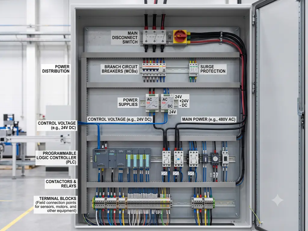
Antes de que un cuadro de control pueda realizar cualquier función inteligente, necesita energía: limpia, protegida y distribuida a todos los dispositivos que hay dentro del armario. La distribución de la energía funciona como un sistema de defensa de tres niveles. El nivel principal de aislamiento apaga todo de golpe. El nivel de protección de las derivaciones aísla los circuitos individuales cuando surge algún problema. La protección a nivel de dispositivo protege los componentes más sensibles y costosos.
Interruptor general y disyuntores: la primera línea de defensa
El seccionador principal es el dispositivo de seguridad más importante de cualquier cuadro eléctrico. Si se desconecta, nada de lo que haya a continuación recibe tensión. En los cuadros industriales, los seccionadores principales gestionan una alimentación de entrada de entre 100 A y 800 A y deben tener una posición de «OFF» bloqueable. Tanto la norma NFPA 79 (sección 5.3) como la norma IEC 60204-1 (sección 5.3) lo exigen: el personal de mantenimiento debe bloquear físicamente el cuadro antes de tocar nada en su interior.
Los interruptores de circuito derivados se sitúan aguas abajo, protegiendo circuitos individuales. La elección entre un MCB y un MCCB depende de la corriente de fallo. Los MCB admiten una capacidad de interrupción de hasta unos 10 kA en entornos industriales. Los MCCB entran en acción a partir de los 25 kA, con ajustes de disparo térmico regulables que oscilan entre 0,7 y 1,0 veces la corriente nominal. Dimensiona el dispositivo principal para que sea, como mínimo, de 125% de la suma de todas las intensidades nominales de los interruptores de derivación; así dispondrás de margen sin incurrir en gastos excesivos.
Para las cargas de motores, utilice interruptores de uso general con clasificación en caballos de potencia que cumplan tanto los requisitos de amperios como los de caballos de potencia. La edición de 2024 de la norma NFPA 79 los incluye ahora explícitamente como medios de desconexión aceptables.
Fusibles y protección complementaria: los guardianes silenciosos
Los fusibles tienen una ventaja sobre los interruptores: reaccionan en microsegundos ante corrientes de fallo extremas. Al no tener piezas mecánicas, no hay nada que pueda fallar y impedir su apertura. Un fusible de clase J limita una corriente de cortocircuito de 200 000 A a una fracción de su potencial destructivo gracias a su característica de paso de corriente I²t. Ningún interruptor de la misma clase de tamaño puede igualar eso.
La desventaja: un fusible solo funciona una vez. Los interruptores automáticos se reinician; los fusibles se sustituyen. La respuesta práctica no es “elige el mejor”. Utiliza interruptores automáticos en los circuitos derivados que puedan dispararse durante la puesta en marcha y requieran un reinicio rápido. Utiliza fusibles en los circuitos en los que un fallo podría destruir los equipos situados más adelante antes incluso de que el interruptor automático comience a abrirse. Ambos deben estar en el mismo cuadro eléctrico, desempeñando funciones diferentes.
Reacciona en microsegundos. No tiene piezas mecánicas que puedan fallar. Ideal para circuitos en los que la corriente de fallo podría destruir los equipos antes de que se dispare el interruptor. De un solo uso: hay que sustituirlo tras el disparo. Menor coste inicial.
Se puede reiniciar tras la desconexión. Ideal para circuitos derivados que puedan desconectarse durante la puesta en servicio. Reacción más lenta que los fusibles ante corrientes de fallo extremas. Mayor coste inicial, coste de sustitución nulo.
La protección contra sobretensiones merece una partida presupuestaria propia. Cualquier cuadro con cableado de campo que salga del edificio debe contar con un dispositivo de protección contra sobretensiones (SPD) de tipo 2 con una capacidad nominal de descarga de 20 kA (forma de onda de 8/20 μs, según la norma IEC 61643-11). La actualización de 2024 de la norma NFPA 79 estableció la obligatoriedad de los dispositivos de protección contra sobretensiones (SPD) para la maquinaria industrial con circuitos de enclavamiento de seguridad, ya que las sobretensiones provocadas por los rayos en el cableado de campo causan fallos reales que se pueden prevenir.
Transformadores y fuentes de alimentación: una tensión que tiene sentido
Un cuadro de control típico funciona con dos o tres niveles de tensión. Los accionamientos del motor principal consumen 480 V CA. Los circuitos de control y las bobinas de los contactores funcionan a 120 V CA. El PLC, los sensores y la interfaz hombre-máquina (HMI) necesitan 24 V CC. El transformador de control y la fuente de alimentación para carril DIN se encargan de toda la conversión.
Dimensionar un transformador de control implica tener en cuenta algo más que la carga en estado estacionario. Cuando se activa la bobina de un contactor, esta consume entre 10 y 30 veces su corriente de mantenimiento durante unos pocos milisegundos. Si el transformador se dimensiona exactamente en función de la suma de las corrientes de mantenimiento, esos picos de corriente de arranque simultáneos provocan una caída de tensión lo suficientemente pronunciada como para que se desconecten otros contactores. Un factor de seguridad de 1,25× es el mínimo imprescindible, no una simple recomendación.
En el raíl de 24 V CC, las fuentes de alimentación conmutadas para carril DIN, con potencias comprendidas entre 15 W y 480 W, son las más utilizadas. No aceptes nada por debajo de una eficiencia de 85%: el calor residual dentro de una carcasa que ya está caliente genera un problema térmico que no habías previsto. Para aplicaciones críticas, elige fuentes de alimentación con un tiempo de mantenimiento de al menos 20 ms a carga nominal, tal y como exigen las normas IEC. Si el tiempo de inactividad es inaceptable, la configuración estándar consiste en fuentes de alimentación redundantes en paralelo con módulos ORing de diodos.
Bloques de distribución eléctrica y barras colectoras: distribución sin caos
Una vez que la tensión eléctrica alcanza el valor adecuado, debe llegar a decenas de dispositivos. Los bloques de distribución de energía reciben un conductor de entrada de gran tamaño y lo dividen en múltiples terminales de salida; en esencia, se trata de un divisor de corriente con una potencia nominal de 600 V y cientos de amperios.
Las barras colectoras admiten corrientes más elevadas. La capacidad de corriente de una barra colectora rectangular de cobre se calcula siguiendo una fórmula aproximada: el área de la sección transversal en mm² multiplicada por un factor de entre 1,2 y 1,5. Una barra de cobre de 100 mm² admite aproximadamente entre 120 A y 150 A, aunque la cifra exacta varía en función de la temperatura del recinto. La norma IEC 61439-1 limita el aumento de temperatura a 65 K para el cobre estañado y a 105 K para el cobre desnudo. Si se superan esos límites, el metal se degrada con el paso de los años de funcionamiento, lo que provoca un fallo del aislamiento.
La codificación por colores se ajusta a la norma IEC 60445: negro para los conductores de fase de CA, azul para el neutro y verde-amarillo para la toma de tierra de protección. Una identificación errónea del neutro en una instalación multinacional provoca una avería cuya localización puede llevar días. Asegúrate de que los colores sean los correctos desde el primer día.
Control y procesamiento — La capa de inteligencia
La potencia hace que las cosas se muevan. El control determina cuándo, cómo y en qué condiciones. La capa de control se divide en dos niveles: la capa lógica procesa la información y toma decisiones, y la capa de conmutación ejecuta esas decisiones a niveles de potencia que la capa lógica no puede gestionar directamente.
Módulos PLC y de E/S: el cerebro programable
El PLC se especifica de forma errónea en dos sentidos opuestos —sobreespecificado e infraspecificado— y ambos suponen un coste real. Un PLC consta de cuatro componentes principales: la CPU que ejecuta el programa, el módulo de alimentación, los módulos de E/S digitales para señales de encendido/apagado y los módulos de E/S analógicos para señales continuas, como la temperatura o la presión.
Empieza por el recuento de E/S. Haz una lista de todos los sensores, interruptores, válvulas e indicadores a los que está conectado el panel. Cuéntalos todos. Añade una capacidad de reserva de 15%; no es un lujo, ya que un panel sin E/S de reserva está a un solo fallo de sensor de tener que realizar un recableado, en lugar de un simple cambio de terminal de cinco minutos. Una máquina con 40 entradas digitales y 24 salidas digitales necesita al menos 6 entradas de reserva y 4 salidas de reserva previstas desde el principio.
La velocidad de barrido determina la rapidez con la que reacciona el PLC. Un PLC pequeño con un tiempo de barrido de entre 1 y 10 milisegundos es suficiente para la mayoría de los controles de máquinas. Las aplicaciones de proceso con variables que cambian lentamente, como los niveles de los depósitos, admiten tiempos de barrido de entre 10 y 100 ms. Para el recuento a alta velocidad o el control de posición, comprueba el tiempo de respuesta a las interrupciones de la CPU; la especificación del ciclo de barrido por sí sola no ofrece una visión completa.
Las señales analógicas se ajustan a las normas industriales. El bucle de corriente de 4-20 mA es el más utilizado, ya que permite transmitir la señal a lo largo de 100 metros de cable sin apenas pérdida de precisión. Compárese esto con las señales de 0-10 V, cuya precisión comienza a degradarse a partir de unos 10 metros, ya que la resistencia de la línea reduce la tensión. Los sensores RTD Pt100 y los termopares (tipos K, J y T) se utilizan para la medición de la temperatura: los RTD para precisiones por debajo de los 600 °C y los termopares para rangos más altos.
Toda la programación de los PLC se ajusta a la norma IEC 61131-3, la norma internacional que define cinco lenguajes: diagrama de escalera, diagrama de bloques de funciones, texto estructurado, lista de instrucciones y diagrama secuencial de funciones (PLCopen). La edición de 2025 incorporó compatibilidad con cadenas UTF-8 y funciones orientadas a objetos, lo cual resulta relevante si el PLC del panel intercambia datos con sistemas empresariales.
Relés y temporizadores: los elementos clave de la conmutación
El relé es el componente activo más antiguo de cualquier cuadro de control, y va a seguir ahí. Las salidas del PLC generan señales de baja potencia: 24 V CC a unos pocos cientos de miliamperios. No pueden alimentar directamente el contactor de un motor de 480 V. Un relé intermedio sirve de puente: la salida del PLC alimenta una pequeña bobina de relé, y los contactos de ese relé activan la bobina del contactor con la tensión y la corriente que sea necesaria.
En casi todos los cuadros eléctricos aparecen cinco tipos de relés. Los relés de control de uso general gestionan la lógica básica de encendido/apagado con capacidades de contacto de entre 5 A y 10 A. Los relés temporizados añaden retardo: el retardo de encendido se activa cuando la bobina se energiza, el retardo de apagado se activa cuando se desenergiza y el modo de intervalo genera pulsos en la salida durante un tiempo fijo. Los relés de seguridad pertenecen a una categoría totalmente diferente: los contactos guiados a la fuerza y la arquitectura interna redundante garantizan que un solo contacto soldado no pueda provocar una situación de inseguridad.
Los relés de estado sólido compiten con los electromagnéticos en la conmutación de alta frecuencia. Un SSR conmuta millones de veces sin desgaste mecánico. La vida útil eléctrica de un relé electromecánico se reduce de aproximadamente 1,5 millones de operaciones a plena carga a quizás 200 000 en condiciones adversas. El inconveniente: los SSR tienen una fuga de entre 1 y 5 mA en estado de apagado en el caso de los tipos de CA, lo suficiente para que un indicador LED brille tenuemente cuando se supone que el circuito está apagado. Esto ha confundido a más de un técnico de puesta en marcha.
Hay una regla de cableado que es más importante que todas las demás en el caso de los relés. Toda bobina de relé de corriente continua necesita un diodo de retorno. Toda bobina de relé de corriente alterna necesita un amortiguador RC. Si se omiten estos componentes, el impulso inductivo que se produce cuando la bobina se desmagnetiza genera un pico de tensión que destruye el transistor de salida del PLC. Esta es la causa más habitual de fallo de los módulos de salida de los PLC en los cuadros nuevos: no se trata de un defecto de diseño, sino simplemente de la falta de un diodo que cuesta dos céntimos.
Control de motores y accionamientos: de la señal al movimiento
Los motores son los que soportan las cargas más pesadas en la mayoría de los cuadros eléctricos. El control de los motores abarca desde la simple conmutación de encendido/apagado hasta la regulación precisa de la velocidad y la posición. Es la aplicación —y no el presupuesto— la que determina en qué punto de este espectro te encuentras.
Contactores y arrancadores de motor: la fuerza que los pone en marcha y los detiene
Un contactor es un relé de alta resistencia diseñado para conmutar corrientes de motor. Sin embargo, la corriente nominal por sí sola no indica si es adecuado para la aplicación. La variable clave es la categoría de utilización definida por la norma IEC 60947-4-1.
AC-1 es adecuado para cargas resistivas o ligeramente inductivas, como calefactores — de uso ligero. AC-3 abarca el arranque y la parada de motores de jaula de ardilla durante el funcionamiento normal; este es el valor predeterminado para la mayoría de las aplicaciones. Un contactor clasificado para AC-3 soporta aproximadamente entre 1 millón y 1,5 millones de operaciones a plena carga. AC-4 abarca el acoplamiento, el avance por pasos y la inversión de marcha —el servicio más exigente, en el que el contactor interrumpe repetidamente la corriente de arranque del motor, que es de entre 6 y 8 veces la corriente de arranque a plena carga (FLC)—. El mismo contactor clasificado para 1 millón de operaciones AC-3 puede que solo resista 200 000 ciclos AC-4. Si la aplicación implica inversiones frecuentes, reduzca la capacidad entre un 50 % y un 70 % — o adquiera desde el principio un contactor diseñado para AC-4.
Un arrancador de motor combina un contactor con un relé de sobrecarga en un único conjunto coordinado. Esta combinación es obligatoria: todo circuito de motor necesita tanto conmutación como protección. El uso de un contactor de un fabricante con un relé de sobrecarga de otro anula la certificación de coordinación. Ejemplo concreto: para un motor trifásico de 7,5 kW y 400 V que consume aproximadamente 14,5 A de corriente nominal de carga (FLC), se debe seleccionar un contactor con una clasificación AC-3 de al menos 16 A, junto con un relé de sobrecarga ajustado a la FLC real del motor. No se trata de una estimación redondeada, sino del valor medido.
Relés de sobrecarga y arrancadores suaves: protegiendo lo que gira
La quemadura del motor es uno de los fallos puntuales más costosos que pueden producirse en un cuadro de control, y casi siempre se puede prevenir. La protección contra sobrecargas se encarga de la amenaza a largo plazo: una corriente ligeramente superior al valor nominal que va deteriorando el aislamiento del devanado a lo largo de semanas o meses. La ley de Arrhenius se aplica directamente en este caso: por cada 10 °C que el devanado supere su clase de temperatura nominal, la vida útil del aislamiento se reduce a la mitad.
Los relés térmicos de sobrecarga utilizan una banda bimetálica que se dobla con el calor, imitando el propio comportamiento térmico del motor. La clase de disparo, según la norma IEC 60947-4-2, determina la rapidez con la que reaccionan: la clase 10 se dispara en 10 segundos a seis veces la corriente nominal; la clase 20, en 20 segundos; y la clase 30, en 30 segundos. La clase 10 es adecuada para la mayoría de los motores estándar. Las clases 20 o 30 son adecuadas para cargas de alta inercia que necesitan más tiempo para acelerar sin que se produzcan disparos indeseados.
Los relés electrónicos de sobrecarga incorporan detección de pérdida de fase y detección de fallos a tierra, unas prestaciones que los relés térmicos simplemente no pueden ofrecer. Si el cuadro eléctrico cuenta con monitorización remota, los datos de diagnóstico por sí solos ya justifican la diferencia de coste.
Los arrancadores suaves abordan un problema diferente: el impacto mecánico y la caída de tensión que se producen en el arranque directo a la red, en el que la corriente de arranque alcanza entre 6 y 8 veces la corriente nominal de funcionamiento (FLC). Un arrancador suave reduce esa cifra a entre 2 y 4 veces la FLC, aumentando la tensión de forma gradual durante un intervalo ajustable de entre 0 y 60 segundos. En el caso de una bomba de agua, la diferencia entre el arranque directo y el arranque suave es la misma que hay entre tener que sustituir los acoplamientos de las tuberías cada dos años y hacerlo cada diez.
Variadores de frecuencia y servoaccionamientos — Control de movimiento de precisión
Los variadores de frecuencia controlan la velocidad del motor variando tanto la frecuencia de salida como la tensión. La frecuencia portadora —ajustable entre 2 kHz y 16 kHz— determina el equilibrio: unas frecuencias más altas se traducen en motores más silenciosos, pero también generan más calor en el propio variador.
Hay un detalle que se pasa por alto constantemente: cuando el cable que conecta un variador de frecuencia (VFD) con su motor supera los 50 metros, los fenómenos de ondas reflejadas producen picos de tensión en los terminales del motor de hasta el doble de la tensión del bus de corriente continua. Un filtro dV/dt en la salida del VFD no es opcional a esa distancia, ya que protege el aislamiento de los devanados del motor frente a un fallo que, aunque parezca misterioso, tiene una causa conocida y evitable.
Los servoaccionamientos aportan precisión al cerrar tres bucles de control —posición, velocidad y par—, cada uno con frecuencias de respuesta que van desde los 100 Hz hasta más de 1 kHz. La diferencia es sencilla: si la aplicación debe detenerse en una posición exacta en todo momento, necesita un servoaccionamiento; si solo tiene que funcionar a una velocidad controlada, basta con un variador de frecuencia (VFD). Una cinta transportadora lleva un variador de frecuencia. Un robot de «pick-and-place» lleva un servoaccionamiento. Una elección errónea no solo supone un gasto innecesario, sino que la máquina no funcionará.
Interfaz de operador y supervisión: la conexión humana
La interfaz de usuario convierte una caja metálica silenciosa en algo que una persona puede utilizar. Aquí no hace falta ninguna teoría profunda, solo decisiones meditadas sobre qué elementos incluir en la puerta.
La pantalla táctil de la interfaz hombre-máquina (HMI) actúa como pantalla principal. Los tamaños más habituales oscilan entre las 7 y las 15 pulgadas en diagonal, siendo necesaria una protección del panel frontal de grado IP65 o IP66 para entornos en los que se realiza un lavado a presión. El protocolo de comunicación de la HMI debe ser compatible con el del PLC: EtherNet/IP, Modbus TCP y PROFINET cubren la gran mayoría de las instalaciones.
Los pulsadores y los interruptores selectores siguen el orificio de montaje estándar de 22 mm según las normas IEC. En los mercados NEMA se utiliza el de 30,5 mm. No son intercambiables: un pulsador de 22 mm se cae directamente a través de un orificio de 30,5 mm. La codificación por colores sigue una convención universal: rojo para parada y parada de emergencia, verde para arranque, amarillo para reinicio o atención, azul para funciones auxiliares, blanco o negro para uso general. Un pulsador de parada de emergencia no es simplemente de color rojo. Debe tener una cabeza en forma de seta, contactos normalmente cerrados y un mecanismo de enclavamiento positivo que requiera un giro o tirón deliberado para liberarse. La norma ISO 13850 exige todas y cada una de estas características. Un pulsador rojo con retorno por resorte no es un pulsador de parada de emergencia, sino un pulsador de parada con el color incorrecto.
Las luces indicadoras completan la puerta. Las luces LED rojas, verdes y amarillas sirven para indicar el estado. Añada una alarma sonora o una luz de señalización intermitente cuando el operario no pueda vigilar el panel de forma continua.
Cableado, terminación e infraestructura física: el esqueleto
Toda la inteligencia del mundo no sirve de nada si los componentes no se pueden montar de forma segura, cablear correctamente y a los que se pueda acceder para su mantenimiento.
La carcasa es la capa más externa. Su clasificación NEMA o IP es la primera decisión de diseño. La NEMA 1 ofrece protección básica en interiores. La NEMA 4 —equivalente aproximadamente a IP66— resiste el agua proyectada con manguera y es el estándar para entornos de alimentación y bebidas. La NEMA 4X añade resistencia a la corrosión. El acero inoxidable 304 es el material predeterminado para el lavado; el 316L, para la exposición a productos químicos agresivos; y el acero al carbono con recubrimiento en polvo, para la mayoría de entornos industriales en interiores. Dimensiona la carcasa para los componentes actuales más un espacio adicional de 30% para futuras ampliaciones. Los paneles abarrotados se sobrecalientan y dificultan cualquier intento de mantenimiento.
En el interior, todo se monta en dos sistemas. La placa trasera soporta los componentes pesados —variadores de frecuencia, transformadores, contactores grandes— atornillados a un subpanel de acero. El carril DIN, con un ancho estandarizado de 35 mm según la norma IEC 60715, soporta todo lo demás: los bloques de terminales, los relés, las fuentes de alimentación pequeñas y los módulos de PLC se encajan a presión en el mismo carril.
Las regletas de bornes se presentan en cuatro tipos prácticos. Las regletas de paso establecen conexiones directas. Las regletas de tierra —de color verde-amarillo, conectadas a la toma de tierra de protección de la caja— se encargan de la conexión a tierra. Las regletas con fusible incluyen un fusible integrado para la protección del circuito a nivel de los bornes. Las regletas multinivel apilan dos o tres conexiones en el mismo espacio, lo que ahorra espacio en el carril. Los conductos para cables guían los cables entre las filas de bornes y dispositivos. Mantén el llenado por debajo del 40% de la sección transversal del conducto: el espacio restante sirve para la disipación del calor y para los cables que alguien añadirá dentro de tres años.
La entrada de cables es lo que distingue a un cuadro eléctrico profesional de uno amateur. Cada cable que atraviesa la pared de la caja debe contar con un prensaestopas con una clasificación de protección IP, como mínimo, igual a la de la propia caja. Una caja NEMA 4 con una entrada de cables sin sellar equivale, a efectos prácticos, a una NEMA 1 en ese punto de penetración. Etiqueta cada cable por ambos extremos con un número único. El técnico que tenga que solucionar un problema en este cuadro a las 2 de la madrugada dentro de tres años te lo agradecerá o te maldecirá en función de esta decisión.
Sistemas medioambientales y de seguridad: protección del panel y de su personal
La mayoría de las listas de componentes mencionan la seguridad de pasada —una línea en el apartado “Pulsadores”—. Esto no hace justicia a una disciplina que cuenta con sus propias normas, su propia categoría de componentes y su propia metodología de diseño.
Gestión térmica
El calor merma la fiabilidad de los paneles de control de forma lenta y silenciosa. Un panel que funcione en una fábrica del sudeste asiático a 40 °C, con variadores de frecuencia (VFD) y fuentes de alimentación que generan calor en su interior, puede alcanzar temperaturas internas superiores a los 60 °C. En ese momento, las CPU de los PLC se comportan de forma errática, los condensadores de las fuentes de alimentación se deterioran a un ritmo tres veces superior al nominal y el tiempo medio entre fallos de todos los componentes electrónicos se reduce drásticamente.
Existen tres estrategias de refrigeración que se adaptan a la carga térmica. Un ventilador con filtro que expulsa el aire caliente resulta eficaz para cargas térmicas de hasta unos 50 W por grado Celsius de aumento de temperatura admisible. Un intercambiador de calor aire-aire mantiene la carcasa sellada —algo necesario en entornos polvorientos o corrosivos— al tiempo que transfiere el calor a través de una barrera. Un sistema de aire acondicionado para toda la carcasa es adecuado para paneles de alta densidad de potencia en entornos calurosos.
La condensación es la amenaza que menos gente prevé. Cuando un panel se enfría durante la noche en un clima húmedo, la humedad interna puede alcanzar el punto de rocío y formarse gotas de agua en las placas de circuitos. Un calentador para armarios de entre 100 W y 300 W con un controlador higrostático cuesta mucho menos que el tiempo de inactividad que evita.
Sistemas de seguridad
La seguridad es una disciplina de control en sí misma. Un relé de seguridad no es simplemente un relé con una carcasa amarilla. Utiliza contactos guiados por fuerza en una configuración redundante: si se produce una soldadura entre contactos, el circuito de supervisión lo detecta y bloquea el siguiente ciclo. Cuando la aplicación requiere tres o más funciones de seguridad —un circuito de parada de emergencia, una cortina fotoeléctrica y un enclavamiento de puerta—, un PLC de seguridad agrupa lo que, de otro modo, serían varios relés de seguridad independientes, lo que reduce el cableado al tiempo que se mantiene el nivel de integridad de seguridad requerido.
Los niveles SIL (según la norma IEC 61508) y PL (según la norma ISO 13849-1) cuantifican la fiabilidad de las funciones de seguridad. El nivel SIL 2 se corresponde aproximadamente con el nivel PLd y abarca la mayor parte de la maquinaria industrial. El nivel SIL 3 se corresponde con el nivel PLe en aquellas aplicaciones en las que un fallo puede provocar lesiones graves.
La norma NFPA 79 regula la seguridad eléctrica de la maquinaria industrial en Norteamérica. La edición de 2024 introdujo requisitos de ciberseguridad para los sistemas de control relacionados con la seguridad y la protección obligatoria contra sobretensiones en los circuitos de enclavamiento de seguridad (NFPA 79-2024). Las etiquetas de advertencia sobre arcos eléctricos, conforme a la norma NEC 110.16 —en las que se indica la energía incidente en cal/cm² y la categoría de EPI requerida—, se colocan en todos los cuadros eléctricos antes de su envío.
Comunicación, percepción y sistemas extendidos: el sistema nervioso
Un panel de control que no puede comunicarse ni detectar su entorno es una isla. Los paneles modernos son nodos de una red que abarca toda la planta.
Los conmutadores Ethernet son el componente de red más sencillo: se pueden montar en carril DIN y cuentan con entre 5 y 16 puertos. Los conmutadores no gestionados se encargan de redes sencillas; los conmutadores gestionados añaden segmentación VLAN y redundancia en anillo. Las pasarelas de protocolo intervienen cuando los dispositivos utilizan protocolos diferentes, por ejemplo, convirtiendo Modbus RTU a través de RS-485 a Modbus TCP a través de Ethernet, o tendiendo un puente entre PROFIBUS y PROFINET. En las instalaciones sin acceso a la red de la planta, un router industrial 4G o 5G proporciona conectividad SCADA con el mundo exterior.
Los sensores proporcionan “ojos” y “oídos” al panel. Los sensores de proximidad inductivos detectan objetos metálicos sin contacto —son un equipamiento estándar en las líneas de fabricación para comprobar la presencia de piezas—. Los de tipo capacitivo detectan materiales no metálicos. Los sensores fotoeléctricos abarcan distancias más largas con los modos de haz pasante, retrorreflectante o difuso. En cuanto a la temperatura, los sensores RTD Pt100 ofrecen una precisión de ±0,3 °C por debajo de los 600 °C. Los termopares alcanzan temperaturas mucho más altas con una precisión ligeramente inferior. Los transmisores de presión emiten una señal de 4-20 mA proporcional a la presión medida. El punto cero de 4 mA es intencionado: permite al sistema distinguir entre «presión cero» (4 mA) y «cable roto» (0 mA).
Los acondicionadores de señal se sitúan entre las señales brutas de los sensores y las entradas del PLC. Aíslan, rompiendo los bucles de tierra que provocan desviaciones en las mediciones. Convierten, transformando las señales de milivoltios de los termopares en señales estándar de 4-20 mA. Amplifican, elevando las señales de microvoltios de las galgas extensométricas a rangos legibles. Toda señal analógica que se transmita desde un dispositivo de campo a un panel de control debe pasar por un aislamiento galvánico. Las diferencias de potencial de tierra entre dos puntos de una instalación industrial alcanzan fácilmente decenas de voltios, lo cual es más que suficiente para destruir una tarjeta de entrada analógica desprotegida.
De la lista de verificación de componentes a la estrategia de abastecimiento: cómo elaborar una lista de materiales consolidada
Ahora ya tienes una visión completa de lo que incluye un cuadro eléctrico, organizado por funciones, con los criterios de selección que realmente importan. La pregunta que casi ninguna guía de componentes responde es: ahora que sabes lo que necesitas, ¿cómo lo consigues sin perderte en la gestión de proveedores?
Un panel de control típico abarca 12 categorías principales de componentes. Si se adquiere cada categoría a un especialista diferente, se acaba gestionando entre 8 y 15 relaciones con proveedores, cada una con su propio plazo de entrega, cantidad mínima de pedido, calendario de envíos y condiciones de pago. El coste oculto no es el precio unitario de ningún componente en concreto, sino los gastos generales de coordinación: conciliar las fechas de entrega, tramitar múltiples declaraciones de aduana, pagar los costes logísticos de diez paquetes pequeños en lugar de un único envío consolidado y buscar respuestas cuando algo llega dañado y todos los proveedores culpan al transportista.
El marco de clasificación de la lista de materiales (BOM)
Ordenar la lista de materiales según el potencial de consolidación por proveedor:
Nivel 1 — Alto potencial de consolidación (entre 60 y 70% de partidas, entre 35 y 50% del gasto total): Fuentes de alimentación para carril DIN, disyuntores, fusibles, relés, contactores, bloques de terminales, pulsadores, luces indicadoras y sensores de uso general. Se trata de productos estandarizados compatibles entre diferentes marcas. Varios fabricantes producen versiones funcionalmente intercambiables. Un distribuidor multigama puede suministrar la mayoría de ellos desde un único almacén. Es aquí donde la consolidación aporta la mayor ganancia en eficiencia.
Nivel 2 — Potencial de consolidación moderado (entre 15 y 251 TP3T de partidas presupuestarias, entre 25 y 401 TP3T de gasto): PLC, módulos de E/S, variadores de frecuencia y interfaces hombre-máquina. En este ámbito, la dependencia de una marca es mayor: el cliente especifica Allen-Bradley, Siemens o Mitsubishi, y el ecosistema de programación hace que cambiar de marca resulte costoso. Sin embargo, los canales de distribución de estas marcas son amplios, y un proveedor con buenas conexiones puede seguir suministrándolas junto con componentes de primer nivel.
Nivel 3 — Bajo potencial de consolidación (5-10% de partidas, 10-20% de gasto): Cajas a medida, dispositivos de seguridad específicos para cada aplicación, sensores especializados y componentes que requieren certificaciones específicas para cada país. Estos suelen proceder directamente del fabricante original o de un integrador especializado.
Matriz de consolidación de proveedores
| Grupo de componentes | Proveedores habituales (fragmentados) | Objetivo consolidado | Palanca clave para la consolidación |
|---|---|---|---|
| Protección eléctrica (disyuntores, fusibles, SPD, transformadores) | 3–5 | 1–2 | Proveedor que ofrece MCB, MCCB y SPD en un único catálogo |
| Fuentes de alimentación y distribución (fuentes de alimentación para carril DIN, PDB, barras colectoras) | 2–4 | 1 | Fuente de alimentación para carril DIN como categoría principal |
| Control y relés (PLC, relés, temporizadores) | 2–3 | 1–2 | Consolidación de Relay en torno al ecosistema de la marca PLC |
| Control de motores (contactores, variadores de frecuencia, protectores contra sobrecargas, arrancadores suaves) | 3–5 | 1–2 | La certificación de la combinación de contactor y protector contra sobrecargas fomenta el abastecimiento de productos de la misma marca |
| Cableado y estructura (bornes, canaleta para cables, carril DIN, caja) | 3–5 | 1–2 | Terminales y conducto del mismo proveedor; la caja suele ser independiente |
| HMI y sensores (HMI, pulsadores, indicadores, sensores) | 3–5 | 1–2 | Pulsadores, indicadores y sensores de una gama de productos unificada |
Cinco pasos para elaborar una lista de materiales consolidada
2. Asignar cada función requerida a las categorías de componentes que se tratan en esta guía (secciones 1 a 7). Marca lo que corresponda y tacha lo que no.
3. Clasifica cada partida como de nivel 1, 2 o 3 en función de la dependencia de la marca y la sustituibilidad.
4. Busca proveedores que cubran la gama más amplia de categorías de primer nivel. Este es tu proveedor principal: la única relación que sustituye a entre cinco y ocho relaciones con proveedores más pequeños. Da prioridad a los proveedores cuyo catálogo abarque sistemas de protección de la alimentación eléctrica, fuentes de alimentación, relés de control, control de motores e infraestructura de cableado.
5. Identifica por separado las deficiencias de los niveles 2 y 3. A la hora de comparar presupuestos, utiliza la amplitud de la oferta del proveedor principal como criterio de desempate. Un precio unitario ligeramente superior por parte de un proveedor que ya gestiona el 70% de tu lista de materiales puede seguir siendo más ventajoso que incorporar a un nuevo proveedor para el 5% de las partidas.
El objetivo no es contar con un único proveedor para todo. Se trata de reducir la complejidad de la gestión, pasando de una docena de relaciones a dos o tres, y de garantizar que el que se encargue de la mayor parte de tu volumen entregue a tiempo, en todas las categorías y con una calidad constante.
Para los equipos de compras que están creando una cadena de suministro de componentes para paneles de control, trabajar con un proveedor multigama que abarque fuentes de alimentación para carril DIN, distribución de baja tensión, relés, controles industriales, sensores y accesorios de cableado bajo un mismo techo puede reducir el número de proveedores de primer nivel de cinco o más a uno solo, lo que disminuye los gastos logísticos, simplifica la documentación aduanera y acorta el plazo total de aprovisionamiento. OMCH (Zhejiang Hugong Automation) cuenta con un catálogo de productos que abarca 30 categorías y más de 3.000 referencias en estos mismos ámbitos. Consulte la gama completa en omch.com.
Referencias
- PLCopen. “IEC 61131-3: Controladores programables — Lenguajes de programación”.” https://www.plcopen.org/standards/logic/iec-61131-3/
- NFPA. “NFPA 79-2024: Norma eléctrica para maquinaria industrial”.” https://www.nfpa.org/codes-and-standards/nfpa-79-standard-development/79
- IEC. “IEC 61439-1:2020 — Conjuntos de aparamenta de baja tensión”.” https://webstore.iec.ch/en/publication/61439-1
- Citel. “Norma eléctrica NFPA 79 para maquinaria industrial (2024): actualizaciones clave”.” https://citel.us/en/nfpa-79-electrical-standard-for-industrial-machinery-2024
- OMCH. “Fuentes de alimentación conmutadas: series para carril DIN y en carcasa”.” https://www.omch.com/switch-mode-power-supply/
- OMCH. “Distribución de baja tensión: MCB, MCCB, contactores y dispositivos de protección”.” https://www.omch.com/low-voltage-distribution/
- OMCH. https://www.omch.com/



 English
  Arabic
  Turkish
  Russian
  Spanish
  French
  Indonesian
  Portuguese
  Thai
Thai  Vietnamese