


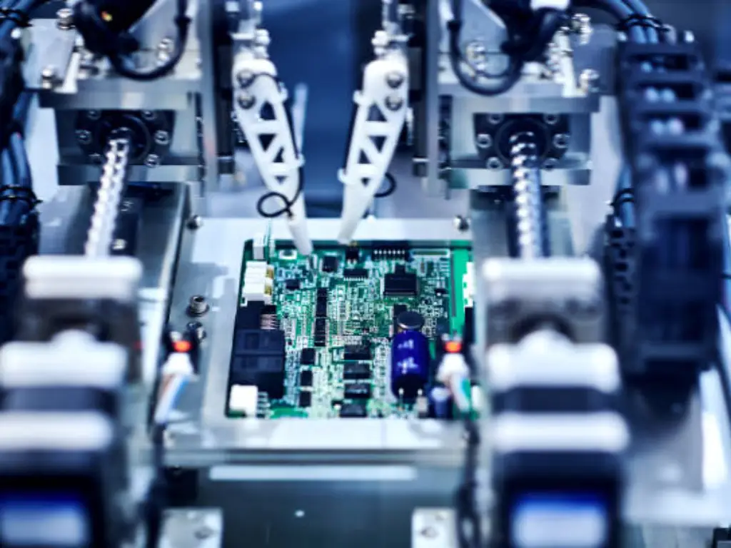
In the rapidly evolving landscape of industrial automation in 2026, the ability to “see” and “sense” with precision is the heartbeat of any smart factory. Whether it is a high-speed packaging line in Munich or a precision semiconductor assembly in Shenzhen, the photoelectric sensor remains the most versatile tool in an engineer’s arsenal across different applications.
But what is photoelectric sensor technology exactly, and what do you do when you have thousands of choices to make to find the right one? This reference is a comprehensive deep-sea exploration of the technology, the operation mechanisms, and the selection criteria that constitute contemporary industrial excellence.
The Physics of Light: How Photoelectric Detection Works
In its simplest form, a photoelectric sensor is a device that involves the emission and reception of light in detecting the presence of an object or the absence of an object, as well as its distance.
Photoelectric sensors are used to overcome the shortcomings of inductive or capacitive sensors which are restricted by the nature of the material (metal or high-dielectric constants) and short sensing distances. By contrast, photoelectric sensors exploit the characteristics of photons to extend the sensing distance between a few millimeters and more than 100 meters.
The Three Pillars of the Sensor
All photoelectric sensors include three main elements:
- The Emitter: Usually a Light Emitting Diode (LED) or a Laser Diode. It produces a light beam that is modulated – pulsed at a certain frequency so as to make it stand out against the background light (sunlight or factory lamps overhead).
- The Receiver: A phototransistor or photodiode which scans the light at the particular frequency emitted by the emitter. When it detects the light (or the lack thereof), it generates a small electrical signal.
- The Evaluation Circuitry: This is the “brain” that amplifies the signal and triggers an output, such as a PNP or NPN transistor switch, to inform the PLC (Programmable Logic Controller) that a target has been detected.

The technology leverages the Internal Photoelectric Effect within a photodiode. When the receiver captures the specific frequency of the modulated light beam, it converts photons into an electrical signal while filtering out ambient interference. In contemporary industrial sensing, we are concerned with the way the target object reacts to this beam of light—whether it breaks it, reflects it, or scatters it.
Master the Three Standard Sensing Operating Modes
The knowledge of the main types of photoelectric sensors is important since approximately 80% of all industrial tasks can be addressed using these settings. Understanding the specific types of photoelectric sensors allows engineers to optimize for cost and reliability.
- Through-Beam (Opposed Mode)
The emitter and receiver are put in two different units that are directly opposite to each other.
- How it works: The emitter sends a constant beam to the receiver. The sensor is activated when an object is “breaking” the beam.
- Pros: Longest sensing range (up to 100m+), high reliability, and effective in dirty environments where dust might block weaker reflections.
- Cons: It needs wiring on both sides of the application, which makes it more difficult to install.
- Retro-Reflective Mode
Both the emitter and receiver are housed together and a separate reflector is positioned opposite the sensor.
- How it works: The light travels to the reflector and returns to the receiver. When this round-trip beam is broken by an object, this object is detected.
- Pros: Only one side needs wiring. It is also cheaper than through-beam over medium distances.
- Cons: Can be fooled by shiny objects (like a polished metal can) that reflect light back to the sensor, mimicking the reflector. (Note: Using a polarized version solves this).
- Diffuse (Proximity) Mode
The emitter and the receiver are housed together and the light is reflected off the target object.
- How it works: The sensor sends out light; if an object moves in front of it, the light bounces back to the receiver.
- Pros: The easiest to install. No reflector or separate receiver needed.
- Cons: The range of sensing is very much dependent on the color, material, and the surface texture of the target. A black rubber tire is far more difficult to notice than a white box made of cardboard.

Beyond Basics: Specialized Modes for Complex Environments
Standard modes sometimes fail when the environment gets “noisy” or the target is “difficult.” To solve these engineering “edge cases,” specialized derivative modes have been developed.
- Precision Targeting: Convergent Beam & BGS
Convergent Beam (Fixed-focus): Unlike standard diffuse sensors that emit a diverging cone of light, convergent beam sensors use an internal lens system to focus the light onto a tiny, high-intensity “sweet spot” at a fixed distance. This enables it to see incredibly small objects (such as a thin wire) and ignore any objects in the background that are only a few millimeters behind the focal point.
Background Suppression (BGS): The developed diffuse sensor. BGS employs Triangulation concepts. Instead of just measuring the amount of light returned, it measures the angle of the return beam using a Position Sensitive Device (PSD) or CMOS array.
- The Problem it Solves: Traditional diffuse sensors are often fooled by color—a white wall far away might look like a black object close up.
- The BGS Advantage: It “sees” the distance, not the color. A black rubber object on a glossy metal conveyor belt is easy to notice as the sensor merely disregards all that exceeds the predetermined distance.
- Solving Visibility: FGS and Clear Object Detection
Foreground Suppression (FGS): FGS is the inverse logic of BGS. It takes a fixed reference point (such as a conveyor belt). When the target is too thin, too dark or too irregular to reflect the light in a proper manner, the sensor is activated since the signal of the belt has been broken. This is the preferred option when it comes to the detection of flat, black plastic components or irregular thin films.
Clear Object Detection: Standard sensors struggle with glass or PET because light passes through them. Polarizing Filters and high-sensitivity circuits are applied by specialized clear object sensors. Their analysis of the minute change in light polarization and intensity through the transparent material gives 100 percent reliable counts in the bottling and pharmaceutical lines.
- Miniaturization and Safety: Fiber Optic and Area Sensors
Fiber Optic Sensors: With the separation of the electronics (the amplifier) and the sensing head through a flexible fiber optic cable, engineers are able to place the eye where it fits in a space as small as a needle. They are immune to EMI (Electromagnetic Interference) and can withstand extreme temperatures, making them ideal for semiconductor furnaces or explosive environments.
Area Sensors (Light Curtains): When a single beam isn’t enough, Area Sensors provide a “curtain of light.” By having several emitter/receiver pairs in one array, they are able to sense objects falling anywhere in a 2D plane. These play a vital role in safety protection and the detection of abnormally shaped objects that may slip through a single point sensor.
Light Source Selection: Infrared, Red LED, vs. Laser
Choosing the right light source is as important as choosing the sensing mode.
| Light Source | Visibility | Sensing Range | Precision | Best For |
| Infrared (IR) | Invisible | High | Medium | Dirty environments, high-power needs |
| Visible Red LED | Clearly Visible | Medium | Medium | General purpose, easy alignment |
| Laser (Class 1/2) | Tiny, Bright Spot | Extreme | Very High | Small parts, long-distance precision |
The laser sensors are the most precise but are more expensive. In the majority of general-purpose applications, a Visible Red LED would be a better choice since it will enable the technician to view the exact location where the sensor is facing when installing it.
Critical Technical Specs Every Engineer Must Know
When comparing data sheets, look beyond the “Sensing Range.” To have a robust system, you must be conversant with the following three measures:
- Excess Gain
One of the most ignored but important specifications in sensor selection is excess gain. It is the ratio of the received light energy to the minimum energy needed to cause the output.
The Formula: Excess Gain = Light Energy Received / Minimum Threshold
A gain of 1.0 is sufficient in an ideal laboratory-clean environment. However, the factory floor is rarely perfect. Dust, steam, oil mist, and lens contamination will all “eat” into your light signal.
- Clean Environments: An excess gain of 1.5x is sufficient.
- Slightly Dirty (Light dust/humidity): Aim for 5x excess gain.
- Extremely Harsh (Heavy smoke, wash-down, or thick dust): You should look for sensors with 10x to 50x excess gain to “burn through” the interference and avoid false triggers.
- Response Time
At high speed sorting, a difference of a few milliseconds can be the difference between a sorted package and a collision. Contemporary sensors usually have response times of 0.5ms to 2ms.
- Output Type: PNP vs. NPN
- PNP (Sourcing): It is common in Europe and North America. The sensor connects the load to the positive voltage.
- NPN (Sinking): Common in Asia. The sensor gives a connection between the load and the negative (ground).
- Note: Many modern sensors now offer “Auto-detect” or “Push-Pull” outputs that work with both.
Industry Applications: Solving Real-World Sensing Challenges
Theory is neat, whereas the factory floor is usually untidy, noisy, and uncontrollable. Success in automation isn’t just about picking a sensor; it’s about choosing a sensing strategy that survives the “grit” of your specific environment.
- Food & Beverage: The Wash-down Challenge
The sensors in this industry are subjected to hot water, steam and harsh cleaning agents on a daily basis.
- Preferred Mode:Polarized Retro-reflective or Clear Object Detection.
- The Scenario: Detecting clear PET bottles or glass jars on a high-speed conveyor.
- Troubleshooting (The “Fog” Factor):
- Problem: Steam or condensation causes the sensor to “see” a solid object when there is none.
- Solution: Use sensors with a high Excess Gain to “burn through” the mist. If false triggers persist, check if the lens is fogged—upgrading to a sensor with a specialized anti-fog coating or a heated lens can solve this.
- The OMCH Edge: To address these wash-down challenges, OMCH’s food-grade series features a fully encapsulated IP69K housing, ensuring that the high-pressure steam mentioned in the troubleshooting section above never compromises the internal electronics.
- Semiconductor & Electronics: The Precision Challenge
When you are dealing with components measured in microns, a standard sensor beam is like trying to perform surgery with a sledgehammer.
- Preferred Mode:Laser Convergent Beam or Fiber Optic.
- The Scenario: Detecting the edge of a silicon wafer or the presence of a 0201-sized resistor.
- Troubleshooting (The “Jitter” Factor):
- Problem: Small vibrations in the machine cause the output to “chatter” (rapidly turn on and off).
- Solution: Adjust the sensor’s Hysteresis or implement a small OFF-delay timer in your PLC logic to stabilize the signal. Ensure the focal point of your convergent beam is exactly on the target path.
- The OMCH Edge: To attain the ultratight spaces, OMCH Fiber Optic sensors provide the “needle-point” accuracy. Since 1986, we have been working on our laser diodes to provide the micron level repeatability that is required by over 72,000 customers in high-tech manufacturing around the world.
- Logistics & Warehousing: The Scale Challenge
The worst enemies in a warehouse are distance, dust and very irregular shapes of packages.
- Preferred Mode:Long-range Through-Beam or Area Sensors (Light Curtains).
- The Scenario: Identifying a pallet that is entering a 50 meter aisle or a cardboard box that has been crushed.
- Troubleshooting (The “Alignment” Factor):
- Problem: The signal loss occurs even at long distances when the mounting bracket is shifted by 1 degree.
- Solution: Have sensors that have a Visible Red LED source so that they can be easily aligned manually. In case the surrounding is very dusty, use an Infrared (IR) source, which is more penetrative to dust particles compared to visible light.
- The OMCH Edge: OMCH has 3,000+ SKUs, which is why it provides “One-Stop” shopping in logistics. It can be a long-range 50m through-beam to keep the safety or a small diffuse sensor to a robotic arm, our 7 production lines make sure that the high-volume orders are completed without compromising on your project schedule.
Why Engineers Trust the OMCH Ecosystem
Beyond the hardware, it’s about the support. Industrial downtime may cost thousands of dollars per minute, and that is why we have created an international infrastructure to support our products:
- Global Presence: 86 branches in China and distributors in 100+ countries are the reason that parts are always close by.
- Rapid Response: We offer 24/7 technical support to help you troubleshoot the “Fog” or “Jitter” factors mentioned above in real-time.
- Certified Quality: Every unit undergoes rigorous inspection to meet IEC standards, backed by a comprehensive one-year warranty.
The OMCH Value: We do not only give you a component but the reliability that will enable you to “set it and forget it”.
Industry 4.0: IO-Link and AI-Powered Smart Sensors
The further into 2026, the more the “dumb” sensor is being substituted with the “smart” sensor. The implementation of the IO-Link technology has transformed the way we communicate with the photoelectric sensors.
- Remote Configuration
Instead of climbing a ladder to turn a tiny potentiometer with a screwdriver, engineers can now adjust sensitivity, timing logic (on-delay/off-delay), and light/dark operate modes directly from the PLC or a smartphone app.
- Predictive Maintenance
Modern smart sensors are able to check their health. When the lens is covered with dust and the excess gain falls below a safe level, the sensor will provide a “dirty lens” warning to the control room before it fails. This prevents unplanned downtime.
- AI-Enhanced Signal Processing
More advanced sensors are now able to employ AI algorithms to differentiate a real target and a “nuisance” reflection of steam, mist, or falling debris, and the number of false triggers in severe industrial settings has been reduced by a significant margin.

Final Selection Checklist: 5 Steps to the Right Sensor
This is the engineering decision path to follow to make sure that you pick the best photoelectric sensor to use in your next project. By responding to these five questions, you will be out of a general classification to a specific part number.
- Define the Target Material and Color
- The Question: What is the surface texture, transparency, and size?
- The Outcome:
- If the object is dark or against a bright background: Choose Background Suppression (BGS).
- If the object is shiny metal or plastic: Choose Polarized Retro-reflective.
- If the object is transparent (glass/PET): Choose a specialized Clear Object Detection model.
- If the object is tiny (SMD components): Choose Convergent Beam or Laser.
- Evaluate the Operating Environment
- The Question: What are the physical conditions of the place of installation?
- The Outcome:
- High-pressure wash-down (Food/Pharma): You must select IP67 or IP69K rated sensors with stainless steel or rugged plastic housings.
- Heavy dust or fog (Sawmills/Foundries): Use Infrared (IR) sources with high Excess Gain (minimum 10x).
- Tight/Confined spaces: Opt for Fiber Optic sensors where the amplifier is mounted remotely.
- Determine the Sensing Distance
- The Question: How much physical space is between the sensor and the target?
- The Outcome:
- Long Range (>10 meters):Through-Beam is the only reliable choice.
- Medium Range (1–5 meters):Retro-reflective with a corner-cube reflector is most efficient.
- Short Range (<1 meter):Diffuse or BGS modes provide the most compact installation.
- Check Electrical & Output Requirements
- The Question: What signal does your PLC or controller expect?
- The Outcome:
- European/North American PLCs: Typically require PNP (Sourcing).
- Asian PLCs: Typically require NPN (Sinking).
- For modern Industry 4.0 setups: Ensure the sensor is IO-Link compatible for digital diagnostic data.
- Analog requirements: If you need to measure exact distance, choose a 0-10V or 4-20mA analog output model.
- Confirm Mechanical Connection & Mounting
- The Question: How will the sensor be wired and maintained?
- The Outcome:
- Easy replacement/Fast maintenance: Use an M8 or M12 Connector type.
- Very tight space/Static installation: Use a Pre-wired Cable to save on connector clearance.
- Heavy vibration: Choose sensors with integrated mounting brackets and high shock resistance.
Conclusion
Photoelectric sensor is a straightforward device with complicated physics. By understanding the interplay between light modes, sources, and technical specifications, you can build systems that are faster, smarter, and more reliable.


