


Simple household appliances and smart appliances, along with factory robots, are complex machines that are dependent on a single small, reliable component: the Micro Switch (officially known as the Miniature Snap-Action Switch). These systems need microswitches.
This is a minor electromechanical device element that is essential. It transforms physical movement, such as pushing a button or a door, into a dependable electrical signal. The most significant characteristic of it is the snap-action mechanism. This design guarantees that the electrical signal is never delayed or wavering, and the lag or electrical chatter that usually impairs a simple switch is entirely eliminated.
In the rest of the article, we shall define micro-switches, describe the mechanism, demonstrate proper micro switch wiring, describe the selection criteria, and describe proper operation and testing.

What is a Micro Switch?
A Micro Switch is a Miniature Snap-Action Switch. It is made up of a very sensitive contact assembly built into a robust enclosure. It is intended to undergo a fast transition of its electrical circuit contact state when a very low physical force,known as the operating force, is exerted on its actuator. Its compact size makes it useful in many devices.
The essential component of the Micro Switch is the Snap-Action mechanism.It is not a gradual action. It is a mechanical necessity that is achieved by an internal over-center spring system. This working principle of a micro switch ensures reliable performance. The spring is pre-stressed. As the actuator travels, the spring bends until it hits a critical point of tipping. When that limit is exceeded the deflected condition of the spring is discharged, and the contacts are driven violently and decisively, regardless of how slowly the actuator was moved.
Key Advantages: Micro Switch vs. Standard Switch
What is the point of having a micro switch when a simple switch is cheaper? Reliability is the key. The low cost of a simple button cannot match the precision offered here.
Snap-Action mechanism cannot be compromised in critical applications. It provides two huge benefits. First, Speed: The contacts part so fast that electrical arcing is not possible to develop or damage the contacts, which significantly extends the life of the switch. This is possible due to the tiny contact gap. Second, Stability: The stored energy ensures that the contacts are forced to connect with a high force against external forces, which results in low resistance and a clean and unambiguous signal each time. This accuracy is critical for safety devices and operational integrity in home applications and similar applications, as illustrated below:
| Scenario | Precision Requirement | Consequence of Using a Standard Switch |
| Microwave Oven Door | Must break circuit within 0.2mm of door release, ensuring that the NC pin functions effectively. | Long stroke allows radiation leakage before power is cut. |
| Elevator Door Lock | Requires 0.1mm precision to confirm lock engagement. This ensures the smooth operation of cylinder drives. | High variability (Hysteresis) risks operational delays or safety issues (e.g., pinching). |
| Automotive Brakes | Must illuminate within 0.3mm of pedal free travel. | A delayed signal increases the risk of a rear-end collision. |
| Industrial Counter | High-speed counting (300cycles/min)requires zero contact bounce. This is often seen in systems handling paper currency. | Short lifespan; high arcing leads to failure after a few tens of thousands of cycles. |
Major Micro Switch Components
We shall divide the essential elements that make it work:
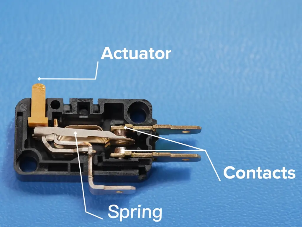
- Actuator: The external part that you push (the Plunger, straight levers, or Roller). This component is one of the different components that determine the required force and distance to activate the switch.
- Snap Mechanism: The main part of the switch, which is the internal springs and pivots that store and release energy.
- Contacts: These are silver alloy contacts or gold alloy parts. The choice of the material depends on the electrical load. For high current applications, the silver alloy is typically used.
- Terminals: These are the external connection points (C, NO, NC) where you connect your wires.
Types of Micro Switches
The various actuator styles and the various designs of lever terminals to optimize each individual actuator style against a specific mechanical input give micro switches different functions. Understanding these different types of micro switches helps in selecting the right component among all types of switches.
Classification by Actuator:
Pin Plunger: The simplest actuator. Offers high precision activation on a short stroke. Applicable in applications that require exact positioning, often used as a direct contact limit switch and can be mounted using a hex nut.

Hinge Lever: Takes advantage of a mechanical advantage. It requires less force than a plunger and is suitable when the object that triggers the action travels longer distances.

Roller Lever: The end of the lever has a roller. Most applicable in applications where the object that activates the switch, e.g. a sliding part or a cam, moves towards the switch at an oblique or frictional angle.

Classification by Contact Material:
- Gold Contacts: To be used in very low current logic or signal level (e.g. less than 50mA) circuits. Gold inhibits oxidation and contamination of low-current contacts.
- Silver Contacts: These are used when the switch is opening or closing large currents (e.g. more than 1A) or when opening inductive loads. Silver alloys are also difficult to weld under load and highly conductive.
How to Choose the Right Switch
The distinction between a micro switch that provides decades of service to a system and a switch that fails in a few months can be explained by the fact that the switch was carefully chosen, taking into account factors like a permanent bearing point for durability. The basic type should not be the only one selected, but the corresponding environmental and load specifications for proper operation. Here are several Major Selection Criteria:
Electrical Load
Decides what current rating is required (5A, 10A, 15A) and what contact material should be used (Gold/Silver). Micro switches are typically rated from 5A (suitable for standard control circuits and relays) up to 15A (necessary for directly switching high-demand inductive loads like small motors and powerful solenoids). Using an undersized current rating will lead to premature failure due to contact welding.
For high-power/high-voltage loads (e.g., motors or a microwave oven), Silver contacts are necessary to handle the arcing. For low-current logic signals (e.g., an LED indicator or PLC input), Gold contacts must be used to ensure signal integrity against oxidation.
Type of Actuator
A type of mechanical component, must fit the movement style of the triggering object. This often relates to achieving longer overtravel. Use a Pin Plunger for applications requiring the highest positional accuracy (like precise limit sensing). Choose a Roller Lever or Hinge Lever when the operating force needs reduction or when the trigger object has a wide range of movement, requiring longer overtravel capacity.
IP Rating
The degree of protection demanded by solid particles and ingress of liquids.
- IP40: Basic protection against objects larger than 1mm. No water protection is offered.
- IP65: Fully dust-tight, protected against water jets from any direction.
- IP67: Fully dust-tight, protected against temporary immersion in water (often used in wash-down areas like food packaging or car washes). This level is often necessary when deploying automation equipment in harsh environments.
What Are Micro Switches Used For?
Status detection is the main objective of a micro switch. It is a little sensor, which responds to a simple Yes/No question of a piece of equipment: Is the part in position?
The application context—whether it’s high-volume consumer goods or precision machinery—fundamentally dictates the switch grade required. As noted previously, Home Appliance switches are optimized for low cost and minimal performance, whereas Industrial Equipment demands extreme endurance, reliability, and environmental protection.
Critical Safety and Interlocks
These applications rely on the switch rapidly and reliably changing its state to prevent accidents or damage.
- Machine Guarding (Industrial-Grade): Used in industrial equipment (like CNC machines). The switch activates instantly when a safety guard opens, cutting all power. Tip: Requires Silver Contacts (15A) and IP67 Sealing for robust load interruption in harsh environments.
- Appliance Interlocks (Appliance-Grade): Used in microwave ovens. The switch confirms the door is safely closed before allowing operation. Tip: Requires Pin Plunger for precise, short-travel engagement and a low-cost design.
Precision Limit and Position Detection
The use of micro switches has unmatched capabilities of detecting precise mechanical limits.
- Homing and Limits (Industrial-Grade): Monitors the exact ‘zero’ position or extremes of axes in 3D printers and automation equipment.Tip: Requires Pin Plunger or precise Roller Lever actuators for extreme positional accuracy.
- Conveyor Systems (Industrial-Grade): Detects product presence, indicates jams, or establishes safe limits for robotic arms. Tip: Often requires a Roller Lever to handle angular contact and IP65 sealing against debris.
System Status and Control Feedback
The switch is necessary to relay essential feedback to a controller regarding the state of the system.
- Electrical Systems (Mixed-Grade): Acts as auxiliary contacts to circuit breakers or provides automotive brake light feedback.Tip: Requires Gold Contacts to maintain the integrity of low-level signal feedback to the controller (PLC/ECU).
- General Appliance Status (Appliance-Grade): Checks if the refrigerator door is closed or the washing machine lid is locked.Tip: Focus should be on low operating force and high mechanical life (not high electrical load).
Industrial Advantage of OMCH: Reliability and Value.
We are concerned with industrial integrity. OMCH micro switches are designed to be robust and work in automation environments and various smart applications. Our micro switches are “Industrial-Priority, Appliance-Compatible” and exactly fit the requirements of ODM/OEM, systems integration and export-oriented businesses.
- Industrial-Scale Capacity, Cost Control: Our micro switches are priced at industrial competitive rates, with 8,000 m² modern factory + 7 automated lines, we give OEMs single-source bargaining power and stable, year-round pricing. These switches allow high volume equipment builders to realize high BOM cost savings.
- Export Compliance, Certification Bundle: We deliver CE, UL, CCC, and RoHS documents along with the product, which saves 2-12 weeks and the cost of certification. It is priceless to OEMs that are involved in rapid cross-border e-commerce distribution.
- One-Stop Basket + Mixed-Item Order: Switches, power supplies, relays and wiring accessories can be combined on the same PO. Pre-shipment cargo volume & weight estimates are provided to help customers optimize container space and reduce freight costs.
- Supply Chain Responsiveness: Our same-day delivery promise on standard orders reduces the risk of line-stoppage to industrial customers who cannot afford the standard lead times of 6-8 weeks of traditional high-end suppliers.
Learning NO, NC, and Common: How to Wire
It is easy to wire the three terminals when you get the logic. Our switches provide you with two functions in one component, which is a key advantage for control switches.
- Three Terminal Design: The layout relies on different electrical terminations.
- C (Common): Where you feed the current. This is the main terminal of the switch. It is also referred to as the Common pin.
- NC (Normally Closed): The default path. This is the NC terminal.
- NO (Normally Open): The default disconnected path.
- Default State – Resting: Current exists between C and NC.
- Actuated State – Pressed: C-NC is broken and C-NO connection is made by the internal mechanism, which performs the opposite function of what occurs in the default state. This action is critical for sequencing control circuits. A simple circuit diagram can illustrate this change. The input pin receives the initial electrical signal.
- Wiring Scenarios:
- Use NO: If you want a device to turn ON when the button is pressed, specifically by pressing the lever of the switch.
- Use NC: For safety circuits. You want the power to flow UNTIL the safety condition is broken (e.g., a door opens).
| Terminal | Default State (Resting) | Actuated State (Pressed) | Function |
| C (Common) | Connected to NC | Connected to NO | Power Input / Common Point |
| NC (Normally Closed) | CLOSED | OPEN | Used for Safety Circuits |
| NO (Normally Open) | OPEN | CLOSED | Used for Activation Circuits |
How to Test Your Micro Switch
The integrity of the micro switch itself should be checked before a system failure is diagnosed. This necessitates a methodical way of testing electrical continuity, ensuring that the limit distance is appropriate.
- Safety First: Turn the power off first! This is non-negotiable. It is important to disconnect power to the system before testing live because it can burn out the multimeter.
- Tool Required: You need a digital multimeter in the continuity range (the one that beeps).
- Step-by-Step Testing:
- Test Resetting Resting C-NC: Place probes on the Common (C) and Normally Closed (NC) terminals. The meter should immediately show continuity (a beep/buzz) to ensure there are no issues with the reset points.
- Test Resting C-NO: Place probes on C and Normally Open (NO). The meter should show no continuity (remain silent). Based on the application, we can use the switch in NO or NC mode.
- Failure Modes:
- Electrical Failure: Welded contacts: The contacts have welded together because of excessive current or arcing, that is, C-NO or C-NC is closed, no matter what the position of the actuator is. This faulty condition is a non-recovery, non-verbal refusal of the intended purpose of the switch.
- Mechanical Failure: The internal spring or mechanism is fatigued or broken, causing the switch to either fail to actuate or fail to reset.
| Test Step | Probes Placed On | Actuator State | Expected Result |
| Step 1 (Resting) | C and NC | Released | Continuity / Beep |
| Step 2 (Resting) | C and NO | Released | No Continuity / Silent |
| Step 3 (Pressed) | C and NO | Pressed | Continuity / Beep |
| Step 4 (Pressed) | C and NC | Pressed | No Continuity / Silent |
Conclusion
The Micro Switch is not just an on/off switch. It is a vital element that is characterized by speed, precision, and endurance. Its reliability is important to system uptime for industrial customers.
Hopefully, we have made it clear why you must insist on industrial-grade specifications. Strong component selections are needed in your system to ensure its success in the long term.
Next Step: Are you now prepared to construct your next machine with the reliability it deserves? [Contact OMCH Technical Support Today] to see our entire line of strong micro switches.


