


The relay may not be an essential, indispensable component that one can imagine in the huge arena of electrical engineering and electronics, but it can be safe to say that it is one of the most basic and adaptable ones. It is a thing which silently allows the intricate power and control of an infinity of systems, starting with the vehicle you so drive or the automated factory that creates the thing you buy every day. However, what is this element of crisis and how does it carry out its most important role?
This tutorial takes an in-depth discussion of electrical relay. We will take it apart to its essential principles, contrast its various variants, review how it has been used in practice, and provide some practical advice on how to choose it, wire it, and troubleshoot it. As either a student or a DIY expert, or an engineer, this in-depth description will arm you with a solid knowledge of the electrical relay.
What Exactly Is an Electrical Relay?
What is a relay? Electrical relay is an electrically operated switch in the most basic meaning. The fundamental application of the relatively small electrical power in one circuit is to regulate the switch (open/close) of another, often much larger circuit and this may include high power or high current. The relay enables a high number of low current control signal to control a high power electrical load. Such ability is not only a convenience; it is a foundation of the contemporary electrical systems and provides three core values:
- Control: Relays offer a safe way to perform the otherwise hazardous task of passing low-voltage, low-current signal, e.g. a signal sent out by a microcontroller or a sensor, or a simple dashboard switch, to control the actions of a high-voltage, high-current device like a motor, a compressor, or a set of powerful lights.
- Isolation (Galvanic Isolation): It is one of the most significant safety elements of a relay. The control circuit (the “input”) and the load circuit (the “output”) are electrickly and physically decoupled. Such isolation avoids transfer back of the high power electrical signals of the load side into the sensitive control electronics, and the equipment connected and the operator.
- Amplification: In actual sense, a relay will serve as a signal amplifier. A milliamp or so of current through a relay relay coil can effectively control a circuit with tens or even hundreds of amperes and therefore the relay can be used to satisfactorily handle inductive loads or even DC loads, including applications with higher currents.
How Relays Work: The Core Principles
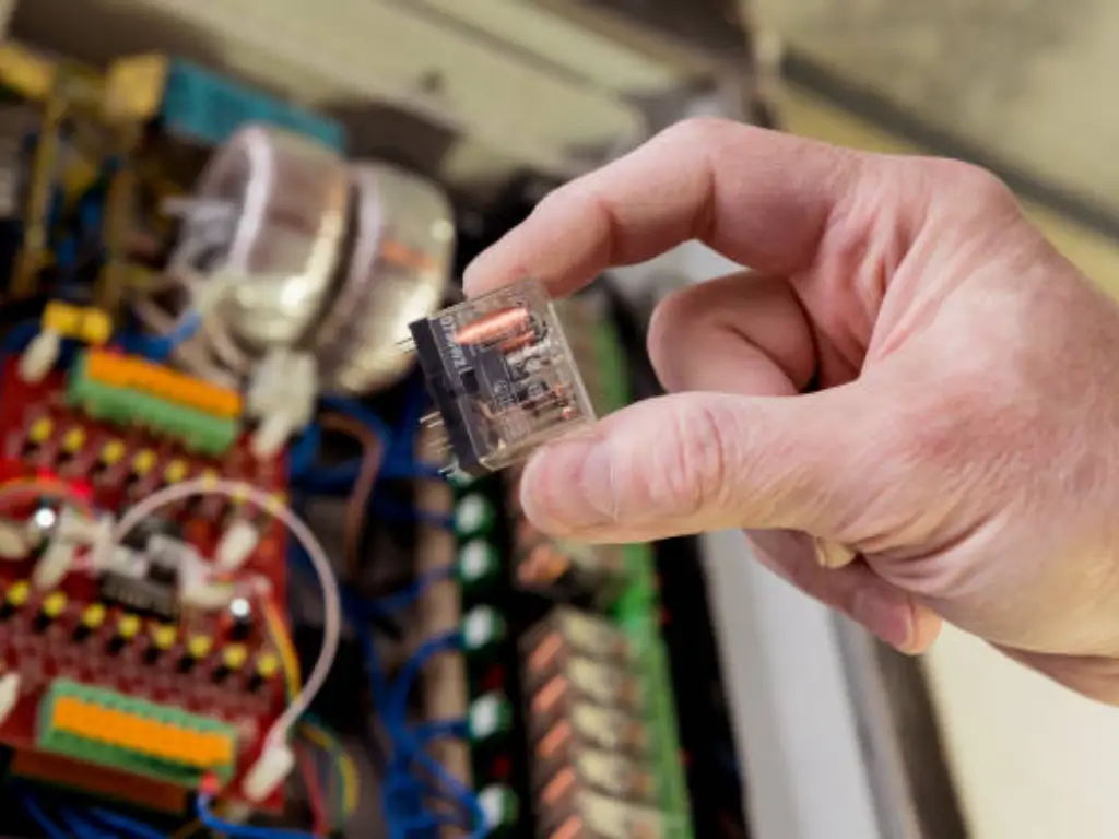
In order to understand relays properly, we need to consider first the most common and natural-like type of relay: the electromechanical relay (EMR). Functioning of it is a real manifestation of electromagnetism at work, and it is used conceptually in formulating other types of relays.
EMR is a complex of multiple elements that should work in collaboration:
- Coil: A cylinder shaped object with a copper wire enclosed by a metal core. As current passes through this wire the core acts temporarily as a magnet, an electromagnet.
- Armature: A moveable part made of iron and gets attracted to the charge that is the electromagnet. It is made to swivel.
- Yoke: A rigid iron structure which offers a low reluctance path to the magnetic flux, based on which the magnetic field is concentrated on the armature.
- Contacts: These are the physical components of the switch which contact each other to form a circuit and if separated it breaks a circuit. The relays are of various types of contacts like normally open contacts (NO) and normally closed contacts (NC). The amount and the nature of contacts depends on the application in question.
- Normally Open (NO): When the relay is not energized the set of contacts are not connected. The circuit is open.
- Normally Closed (NC): This is the reverse of normally open whereby the relay contacts are in contact when the relay is not energized. It is closed.
- Common (COM): The armature is connected to terminal that is moved to the NO or NC contacts.
- Spring: A portion to provide armature to its rest position when the coil is no longer energized.
Mechanical vs. Solid State Relays (SSR)
The electromechanical relay with all its cleverness is a moving-part device. With the technological improvement, there is a completely electronic variant, known as Solid State Relay (SSR). Although they share the overall purpose, the internal makeup and the nature of performance in them is practically dissimilar. This distinction is very important in the design of modern systems.
A SSR does not contain moving parts. The electrical load switching accomplished by it is using semiconductors, specifically thyristors, TRIAC, or power transistors. Such control signal is conventionally connected to the switching semiconductor through an optocoupler (an LED and a photodetector) and this provides absolute galvanic isolation as in an EMR. This enables a secure functioning under more demanding circumstances like a high electrical arc exposure or a necessity to regulate electronic devices.
Here is a detailed comparison between the two:
| Feature | Electromechanical Relay (EMR) | Solid State Relay (SSR) |
| Working Principle | Uses an electromagnet to physically move contacts. | Uses semiconductor switching elements (e.g., TRIACs, MOSFETs) controlled by light. |
| Lifespan | Limited by mechanical wear of moving parts (typically 100k to 10M cycles). | Extremely long, as there are no moving parts to wear out (billions of cycles). |
| Switching Speed | Slower (typically 5-15 milliseconds) due to physical movement. | Extremely fast (microseconds or less), enabling high-frequency applications. |
| Noise | Produces an audible “click” during operation. | Completely silent operation. |
| Vibration Resistance | Susceptible to shock and vibration, which can cause contact bounce. | Highly resistant to shock and vibration. |
| Output Resistance | Near-zero resistance when closed; infinite resistance when open. | Has a small internal voltage drop when on, and a small leakage current when off. |
| Power Consumption | Requires continuous power to the coil to stay energized. | Requires very low input power to operate. |
| Cost | Generally lower initial cost for high-power applications. | Higher initial cost, but can offer a lower total cost of ownership due to longevity. |
| Typical Applications | General purpose switching, automotive, simple control circuits. | High-frequency cycling, industrial automation, medical devices, silent environments. |
As you can see, when an environment of high demands is required with regard to reliability, quick switching and long life span, Solid State Relays are the better option. They can also be used in modern control and automation where their operating nature is silent as well as tough against shock and vibration.
Why Modern Systems Prefer Solid State Relays
At OMCH, we specialize in high-performance Solid State Relays designed for industrial automation. OMCH SSRs, like the OMCH SSR-DA/AA Series, offer precise control and exceptional durability, eliminating issues like contact resistance or the electrical arc that can occur in traditional mechanical relays. This ensures maximum uptime and efficiency for critical applications like lighting control systems or safety systems.
Common Applications and Use Cases
The flexibility of the relays explains why they are used in virtually all the fields of technology. They are also necessary in a large set of applications because of their capacity to safely conduct high currents or DC current:
- In Automotive Systems: A 21st century automobile is a universe of relays. The reasons they are needed is that the car control electronic (ECU, body control module) work on very low currents whereas very high current is required in things such as headlights, starter motors and cooling fans. The relays fill this gap, and the seeming safety and efficiency of the control of these heavy loads through a small switch on the dashboard or a signal of the ECU.
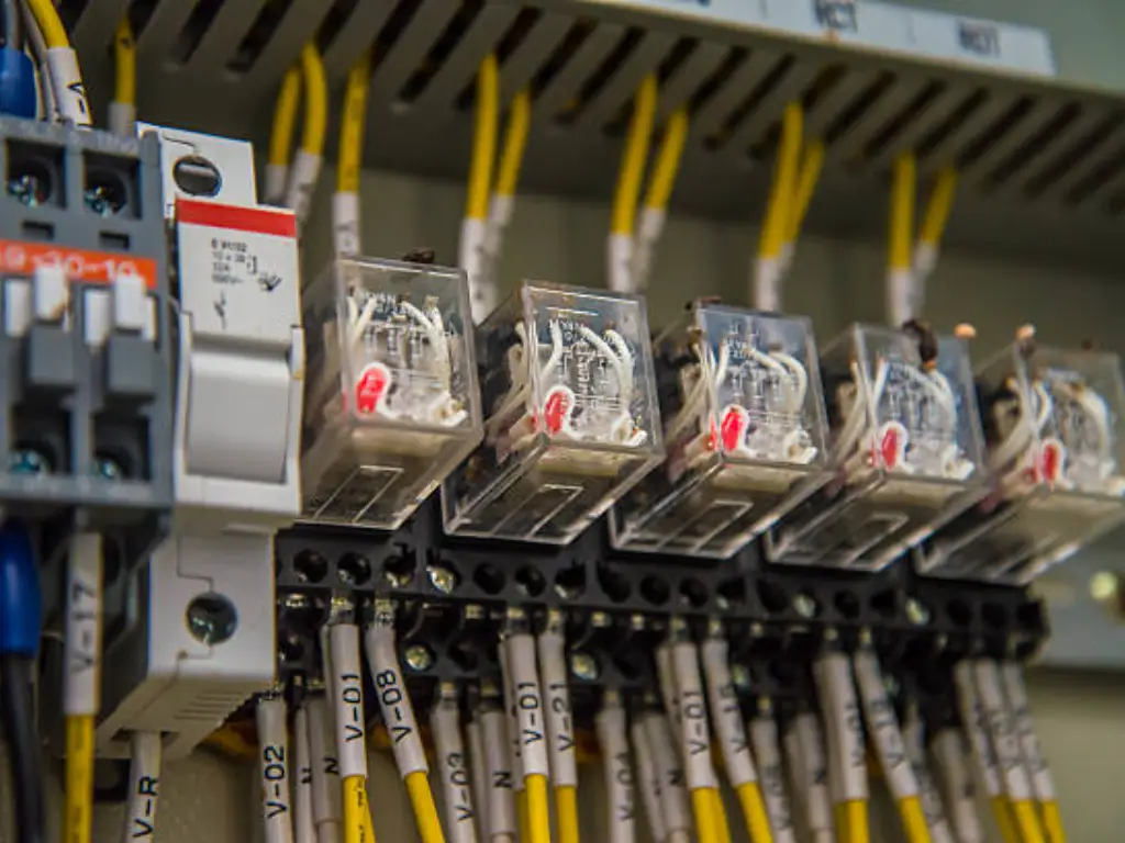
- In Industrial Control Panels: Industrial automation depends to great extent on relays. They are intermediaries in control panel between the high-power equipment on the factory floor and the programmable logic controller (PLC). An example is said to be a 24V DC signal output of a PLC that may activate a relay which in its turn may turn on or off a 480V AC three-phase motor. SSR have special applications here because they have long life in high-cycle uses such as a heater control and motor drives.
- In Smart Home & DIY Projects: In projects where the hobbyist or maker needs to get their projects to communicate to the real world, relays are the answer. A small machine such as a lamp or a coffee maker or household appliance can not be directly powered by a small microcontroller such as an Arduino or Raspberry Pi. With a relay module the microcontroller could be used to safely switch regular AC power that could be found in a house and this layout is the foundation of any smart home or automation project imaginable.
How to Choose the Right Relay
Selecting the correct relay is critical for the safety and reliability of your circuit. It involves matching the relay’s specifications to the demands of your application. Consider the following important factors:
- Load Voltage & Current: It is the most significant specification. What are the voltage (AC or DC) of the device to switch? How much current will it require when it is operating? These values have to be lower than the contact (or output) rating of the relay. Never forget about the 20-30 percent margin of safety.
- Control Signal Voltage: The voltage needed to complete energization of the relay coil (an EMR) or input circuit (an SSR). It has to be able to be equal or greater than the output of your control device (e.g. an Arduino gives 5V, a car battery gives 12V, a PLC gives 24V).
- Switching Frequency: What is the number of times the relay must be switched on and off? In most switching applications (more than once per second) only a Solid State Relay is viable because even an EMR is prone to fail mechanically due to high switching.
- Environmental Factors: The environment of operations. Does there exist any high vibration or shock? Are operation in silence necessary? Are explosive gases involved (where a sealed relay will be necessary)? SSR is usually a better and safer alternative in the highly vibrational environments such as those where silence and high reliability measures are necessary.
A Practical Guide to Relay Wiring
A standard numbering scheme is used to number terminals on most automotive and industrial relays, which simplifies the wiring of such relays. The most frequent ones are:
- 85 & 86: They are the relay coil terminals. The relay will be activated by applying the right voltage on them. Polarity is immaterial in the majority of DC relays although they may have an internal suppression diode, in which case they will be marked.
- 30: The Common terminal. This is generally related with supply of power to the load circuit.
- 87: Normally Open ( NO ) terminal. That is the terminal terminal 30 is driven into when the relay closes.
- 87a: The Normally Closed (NC) contact (on 5-pin relay). This is the end terminal that is connected with terminal 30 when relay is not in action.
Troubleshooting Common Relay Problems
The relay is usually a culprit when a circuit fails, especially if the power source is not functioning properly. Below are some of the issues that are normally experienced and how they are diagnosed:
Problem 1: The relay makes a “clicking” sound, but the load doesn’t work.
- Possible Cause: It means that the control circuit (the coil is being energized) is okay; there is a fault on the load circuit. The internal contacts of the relay might be badly worn or burnt (pitted) so that no good electric contact can be made. Alternatively, this could be due to a badly connected load, a disconnected or broken wire or a blown fuse at the load side (pins 30 and 87).
Problem 2: The relay gets very hot.
- Possible Cause: In the case of an EMR, a coil can only be connected up to a certain voltage before the coil becomes too hot and burns up. In both EMRs and SSRs, in case the relay is too small to handle the load current, the relay will overheat, gradually, and fail.
Problem 3: The relay is always on or always off.
- Possible Cause: In an EMR, a huge current spike may even weld the internal contacts together, leaving the relay in the “on” mode. In its turn, coil wire burned out will not allow it ever to switch on. A large overvoltage or overcurrent condition in an SSR may damagethe internal semiconductor, rendering it permanently open circuit (or anti-fused permanently closed circuit).


