












Beş kişiye mikro anahtarla limit anahtarını birbirinden ayıran şeyin ne olduğunu sorarsanız, üç farklı cevap duyarsınız. Bazıları, ikisinin rakip ürün aileleri olduğunu söyler. Bazıları ise limit anahtarının sadece daha sağlam bir kabukla sarılmış bir mikro anahtar olduğunu söyler. Diğerleri ise limit anahtarının içinde bir mikro anahtar barındırdığını söyler. Bu üç cevap da internette dolaşıyor ve her biri tek başına okunduğunda ikna edici geliyor.
Bu anlaşmazlık, iki terimin farklı sorulara yanıt vermesinden kaynaklanmaktadır. “Mikro anahtar” terimi, bir anahtarın yapısı. “Sınır anahtarı” şu anlama gelir: Bir anahtarın işlevi nedir?. Bunu fark ettiğinizde, çelişkiler ortadan kalkar ve ürün sayfasındaki etikete takılmadan doğru parçayı sipariş edebilirsiniz.
Bu makale, tüm süreci ele almaktadır: isimlerin anlamları, kaynakların neden birbiriyle çeliştiği, elinizdeki arızalı bir parçanın yerine ne seçmeniz gerektiği, hangi teknik özelliklerin gerçekten önemli olduğu ve bu iki ürün serisini stokluyorsanız ya da satıyorsanız kataloğunuzda nasıl yer almaları gerektiği.
“Mikro Anahtar” ve “Sınır Anahtarı” Terimlerinin Gerçek Anlamı Nedir?
Mekanizmadan başlayalım, çünkü “mikro” terimi buradan gelmektedir. Mikro anahtar, teknik terimle minyatür ani hareketli anahtar, bir “over-center” yay etrafında tasarlanmıştır. Aktüatöre bastığınızda yay bükülür ve enerji depolar. Kritik bir devrilme noktasında, aktüatör ne kadar yavaş hareket etmiş olursa olsun, depolanan bu enerji kontakları yüksek hızda birbirine bağlar (mikro anahtar nedir). Asıl önemli olan o ani hareket. Kontaklar, minimum geri sekmeyle, neredeyse anında ve kesintisiz bir şekilde durum değiştirir; bu sayede sinyalde hiçbir zaman titreme olmaz. İşte bu yüzden bir mikro anahtar, bir farede yıllarca tıklamaları algılayabilir ve mikrodalga fırının kapı kilidi, kapı açıldıktan sonra milimetrenin bir kesirinde devresini kesebilir.
“Mikro anahtar” = yapısına ilişkin bir isim
Mikro anahtar hakkında sorular: Nasıl üretilir? Ani hareketli, merkez aşımlı yaylı, kompakt eleman. Bu şekilde üretilen her anahtar, hangi makinede kullanılırsa kullanılsın, bir mikro anahtardır.
“Sınır anahtarı” = bu işle ilgili bir isim
Sınır anahtarı hakkında sorular: Ne işe yarar? Hareket mesafesinin sonunda bulunur ve kontrol sistemine “buraya ulaşıldı” / “bu noktayı geçildi” bilgisini verir. Bu görevi yerine getiren herhangi bir anahtar, hangi mekanizmayı kullanırsa kullansın, sınır anahtarı olarak işlev görür.
Şimdi de “sınır” tarafına gelelim. Hareket anahtarı veya konum anahtarı olarak da adlandırılan bir sınır anahtarı, mekanizmasıyla değil, işleviyle tanımlanır. Bu anahtar, bir makinenin hareket mesafesinin sonuna monte edilir ve hareketli bir parça buraya ulaştığında kontrol ünitesine sinyal gönderir. Bir CNC ekseninde bu sinyal, “başlangıç noktasına ulaşıldı” anlamına gelebilir. Bir konveyörde ise “palet konumunda” anlamına gelebilir. Bir vinçte ise “kanca hareket mesafesinin sonuna ulaştı, şimdi dur” anlamına gelebilir. Aynı işlev her yerde karşımıza çıkar: bir robot kolunu durdurması gereken bir kapı, rayının ötesine geçmemesi gereken bir taşıyıcı, hareket etmeden önce hattın varlığını bilmesi gereken bir palet.
Ve işte kafa karışıklığının çoğunu ortadan kaldıran gerçek şu: bu iki isim birbirini dışlamıyor. Bilgisayar farenizin içindeki küçük, anlık tepkili eleman bir mikro anahtardır. Aynı tür bir elemanı bir makine çerçevesine, bir rayın ucuna sabitlerseniz, o eleman bir limit anahtarının işlevini yerine getirir. Karşılaşacağınız endüstriyel limit anahtarlarının çoğu, aslında sağlam bir gövdeye yerleştirilmiş ani hareketli mikro anahtarlardır. İşte bu yüzden bu terimler sürekli birbirine karışır. Her ne kadar farklı şeyleri tanımlasalar da, aynı fiziksel nesne her iki adı da aynı anda taşıyabilir.
Unutulmaması gereken bir cümle: Mikro anahtar, yapısına ilişkin bir isimdir; sınır anahtarı ise işlevine ilişkin bir isimdir. Bunlar farklı sorulara cevap verir; bu nedenle bunları rakipmiş gibi karşılaştırmak hiçbir zaman tam olarak işe yaramaz.
Devam etmeden önce bir konuyu açıklığa kavuşturalım. CNC veya robotik yazılımlarında sıkça bahsedilen “sınır anahtarı”, sanal bir sınırdır: kontrolörün içindeki programlanmış bir sınırdır, fiziksel bir parça değildir. Bu makale, elinize alıp kablolayabileceğiniz fiziksel anahtarları ele almaktadır.
İnternette Neden Üç Çelişkili Cevap Bulacaksınız?
“Mikro anahtar ve limit anahtarı” ifadesini aradığınızda, en üstte çıkan sonuçlar üç gruba ayrılır. Her grup kendi içinde tutarlıdır ve her biri diğer ikisiyle uyumsuzdur.
1. Kamp: “Bunlar, farklı dünyalar için tasarlanmış farklı ürün aileleridir”
Bazı kılavuzlar, bunları uygulama alanına göre iki kategoriye ayırır: ev aletleri ve elektronik cihazlar için mikro anahtarlar, endüstriyel makineler için limit anahtarları. Bu sınıflandırma kulağa mantıklı gelse de, bir konveyör bandı limit anahtarı ile bir fare mikro anahtarının içlerinde genellikle aynı ani hareket mekanizmasına sahip olduğunu fark ettiğinizde bu ayrım geçerliliğini yitirir. Mekanizmayı belirleyen, uygulama değildir. Önde gelen bir açıklama kaynağı, bir mikro anahtarın NO ve NC olarak bağlanmış “iki limit anahtarından oluştuğunu” bile iddia etmektedir. Bu ifade, gerçek yapıyı tersine çevirmektedir: tek bir eleman, tek bir ortak terminal, iki kontak devresi. Bu durum, kafa karışıklığının ne kadar derinlere inebileceğini göstermektedir.
Kamp 2: “Sınır anahtarı, aslında bir muhafaza içindeki mikro anahtardan ibarettir”
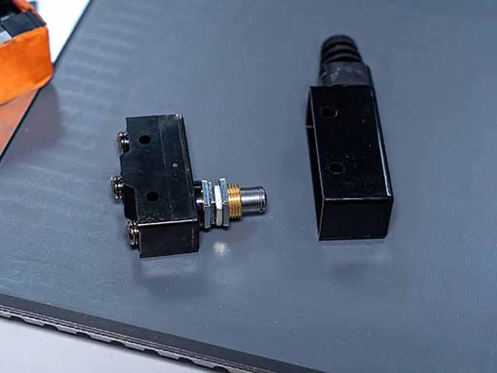
Diğer kaynaklar ise limit anahtarının, plastik veya metal bir kapakla su ve toz geçirmez hale getirilmiş bir mikro anahtar olduğunu belirtir. Bu görüşün arkasında gerçek bir gözlem yatmaktadır: Birçok limit anahtarı, sızdırmaz bir muhafaza içinde ani hareketli bir eleman barındırır. Ancak bu, aşırı genelleme niteliğindedir. Her limit anahtarı mikro anahtar tabanlı değildir. Ağır hizmet tipi tasarımlarda doğrudan etkili veya başka mekanizmalar kullanılabilir; ayrıca bir makine spesifikasyonu temassız algılama gerektirdiğinde, bir yakınlık veya fotoelektrik sensör, hiçbir ani hareket elemanı olmadan “limit” rolünü üstlenir.
Kamp 3: “Bir limit anahtarı, bir mikro anahtar içerir”
Teknik açıdan en titiz kaynaklar tam olarak bunu söylüyor ve bu, çoğu mekanik limit anahtarı için geçerlidir. Ancak bu bilgi sizi yolun yarısına kadar götürür. Pazarın hangi yarısının hangisi olduğunu size söylemez ve arızalı parçanızın üzerindeki isim belirsiz olduğunda ne sipariş etmeniz gerektiğini de belirtmez.
Her şeyi netleştiren merdiven
Üç grup da aynı merdiveni, farklı basamaklarda anlatıyor:
Çıplak ani hareketli eleman — mikro anahtarın kendisi: PCB üzerine monte edilmiş veya ürünün içine klipslenmiş, uçları açıkta.
Eleman + aktüatör + terminallerden oluşan kablolu bir bileşen — yine de bir bileşendir, yine de sızdırmaz değildir.
Kapalı tip limit anahtarı tertibatı — kablo girişi bulunan, IP sınıfı dayanıklı bir muhafaza içinde yer alan ani hareketli eleman; makinelere cıvatalarla sabitlenmek üzere tasarlanmıştır.
Temassız değiştirme — içlerinde mekanik parça bulunmayan yakınlık veya fotoelektrik sensörler, “hareket sonu” işlevini yerine getirir.
- Camp 1, bu merdivenin uçlarını ayrı türler sanmaktadır.
- Camp 2, 2. basamak ile 3. basamak arasındaki atlamayı anlatıyor ve bunu “tüm hikâye” olarak adlandırıyor.
- 3. Kamp, 3. basamağı doğru bir şekilde tanımlamaktadır, ancak bununla sınırlı kalmaktadır.
Pazar yerindeki “mikro limit anahtarı” terimi de buradan gelmektedir. Katalog satıcıları, bu bileşeni ve montaj grubunu tek bir arama dostu kategoride birleştirir. Bunu bir mühendislik kategorisi olarak değil, bir raf etiketi olarak değerlendirin. Ürün adlarını ipucu olarak alın ve bunun yerine işlev, boyutlar ve parametreler açısından doğrulayın.
Ürün yelpazesinde bir üst seviyeye çıktıkça değişen unsurlar arasında koruma özellikleri, montaj seçenekleri ve servis kolaylığı yer alır; fiyat da buna paralel olarak artar. Değişmeyen şey ise sistemin temelini oluşturan anahtarlama mekanizmasıdır. İşte bu nedenle, tek bir makine bir yerde çıplak bir elemanı, başka bir yerde ise kapalı bir montajı taşıyabilir; her ikisi de aynı anlık hareket teknolojisiyle sorunsuz bir şekilde çalışır.
Hangisini Sipariş Etmeliyim? Bir Saha Kontrol Listesi
Elinizde arızalı bir anahtar tutarak bir tezgahın başında ya da hareket mesafesinin sonunda durmuş bir makinenin yanında duruyorsunuz. Asıl soru “mikro ve limit arasındaki fark nedir?” değil. Asıl soru “bu makinenin tekrar çalışması ve çalışmaya devam etmesi için ne sipariş etmeliyim?”
1. Adım: Parçayı üzerinde yazılı adına göre değil, işlevine göre sınıflandırın
Değiştireceğiniz parça hakkında üç soru sorun:
- Nereye monte edilmişti? Toz, yağ ve yıkama suyunun nadiren ulaştığı bir ürünün veya panelin içi mi? Yoksa bunların etkisine tamamen maruz kalan makinenin üzerinde mi?
- Bu ne anlama geliyordu? Bir kapı veya panelin mikro hareketi mi, yoksa bir koruma konumu mu? Yoksa hareket halindeki bir eksenin hareket sonu mu?
- Bu ne tür bir fiziksel yapıdır? Lehim veya vida terminalleri olan küçük, çıplak bir parça mı? Yoksa kablo rakoru bulunan daha büyük, kapalı bir montaj mı?
Cevaplar sizi doğru basamağa yönlendirir. CNC eksenine cıvatalarla sabitlenmiş kapalı bir tertibat, işlev olarak bir limit anahtarıdır. Ürününüzün içindeki çıplak eleman ise şekil olarak bir mikro anahtardır. Eski parçanın plastiğine kalıplanmış kelimeye göre değil, işlevine ve montaj ortamına göre sipariş verin. Yedek parça gelene kadar eski parçayı saklayın: Üzerine damgalanmış model kodu, çapraz referanslar ve tedarikçilerin dayandığı bilgidir; logo veya etiket stili değil.
2. Adım: Herhangi bir şeyi değiştirmeden önce yapmanız gereken dört kontrol
Bir limit anahtarını çıplak bir mikro anahtarla değiştirmek ya da tam tersini yapmak istiyorsanız, şu dört kontrolü gerçekleştirin. Bunlardan herhangi birinde sorun çıkarsa, değiştirme işlemi başarısız olur:
Dört kontrol
Mekanizma — Yedek parça gerçekten ani hareketli mi? Orijinal parça ağır hizmet tipi doğrudan hareketli bir anahtar ise, mikro anahtar çalıştırma hissini ve geri dönüşü olmayan noktayı değiştirir.
Montaj ve yer — Delik düzeni, sabitleme ölçüleri ve aktüatörün erişim mesafesi birbiriyle uyumlu mu? Mikro anahtar elemanı, limit anahtarı tabanı gibi şekilli değildir.
Aktüatör geometrisi — piston, kol mu yoksa silindir mi? Hareketli parça hangi yönden, hangi açıyla ve ne kadar fazla hareketle yaklaşıyor? Uzunluğu yanlış olan bir kol, yanlış konumda tetiklenir.
Bağlantılar ve devre — NO, NC mi yoksa SPDT mi? Gerilim ve akım değerleri orijinal devreninkilerle aynı mı yoksa daha mı yüksek?
#3 kontrolü en sık başarısızlıkla sonuçlanır. İki anahtar dışarıdan bakıldığında aynı görünebilir ancak iç çalışma özellikleri farklı olduğu için (çalıştırma kuvveti, kilitlenme öncesi ön hareket mesafesi ve kilitlenme sonrası aşırı hareket mesafesi) tamamen farklı noktalarda devre dışı kalabilir. Gövde şeklinin aynı olması, devre dışı kalma noktasının da aynı olduğu anlamına gelmez. Bir çapraz referans tablosunda bir modelin uyumlu olduğu belirtildiğinde, güvenli bir şekilde doğrulamanın tek yolu, fotoğrafı değil, teknik özellik belgesindeki çalışma özelliklerini karşılaştırmaktır.
3. Adım: Değiştirilmemesi gereken durumlarda, iki katı sınır
Aşağıdaki iki durum, yukarıdaki tüm kontrollerden önceliklidir.
Anahtar gövdesini asla mekanik durdurucu olarak kullanmayın. Bu, erken arızaların en yaygın nedenidir. Hareketli bir parça anahtara sert bir şekilde çarpar ve baskı yapmaya devam eder; aşırı hareket mesafesini aşarak iç mekanizmayı tahrip eder. Ayrı bir sabit durdurucu takın; böylece anahtar sadece sinyal verir ve makinenin momentumunu asla emmez. Eski parçanız bu şekilde arızalandıysa, yedek parça da aynı şekilde arızalanacaktır.
Bir güvenlik fonksiyonunun yerine asla genel amaçlı bir anahtar kullanmayın. Acil durdurma zincirleri, koruma kilitleri ve diğer güvenlik devreleri, aktüatörün NC kontağını mekanik olarak zorlayarak açtığı, pozitif açılımlı (doğrudan açılımlı) kontak düzenine sahip anahtarlara ihtiyaç duyar. IEC 60947-5-1 standardı, kontrol devresi cihazları için bu özelliği belirtmektedir. Standart bir ani hareketli anahtarın NC kontağı, kontaklar birbirine kaynaklanmış olsa bile kapalı kalabilir; bu da tam olarak bir güvenlik devresinin dayanması gereken durumdur. Ne ürün adı ne de şekli, bir anahtarın bu özelliğe sahip olup olmadığını gösterir. Bunu, teknik veri sayfası ve güvenlik standardı belirtir.
Makineyi suçlamadan önce bir anahtarı nasıl test edersiniz?
Bir multimetre, çalışma tezgahındaki tartışmaların çoğunu bir dakikadan kısa sürede çözüme kavuşturur. Cihazı kapatın. Ölçüm cihazını devamlılık moduna ayarlayın. Üç terminali kontrol edin: ortak (C), normalde açık (NO) ve normalde kapalı (NC).
- C–NC, aktüatör serbest bırakıldığında sürekli durumdadır ve aktüatöre basıldığında açılır.
- C–NO, bırakıldığında açık kalır ve basıldığında devre devamlılığı gösterir.
- Aktüatörün konumundan bağımsız olarak C–NO kapalı kalırsa, kontaklar kaynaklanmıştır: bu durum, aşırı yük veya ark oluşumundan kaynaklanan bir elektrik arızasıdır.
- Düğmeye bastığınızda herhangi bir değişiklik olmazsa, iç yay veya mekanizma yıpranmıştır: bu bir mekanik arızadır.
Test tezgahında sorunsuz çalışan bir anahtar, makine içinde yine de arızalanabilir — bir sonrakini takmadan önce, bir öncekinin arızalanma nedenini kontrol edin. Kaynamış kontaklar, akım değerinin yetersiz olduğuna işaret eder; ezilmiş gövde, sert durdurucuların eksik olduğuna işaret eder; iç kısımdaki korozyon ise ortam için yanlış IP derecesine işaret eder.
Yaygın arıza türleri, gerçek nedenlerle eşleşir. Kaynaklı kontaklar yükün temas değerini aştığı ya da yükün endüktif olduğu ve güç derecesinin düşürülmesi gerektiği anlamına gelir. Parazit veya aralıklı sinyaller Bu, aşınmış veya kirlenmiş kontaklar ya da ön gerginliğini kaybetmiş bir yay anlamına gelir. Çalıştırma yok bu, mekanik yorgunluk ya da iç yayanın kırılması anlamına gelir. Korozyon bu, nemin içeri girdiğini ve anahtarın, içinde bulunduğu ortamdan daha temiz bir dünya için sızdırmaz hale getirildiğini gösterir. Homing işlemini durdurmuş bir CNC ekseninde, bu durum, $200 OEM grubunu değiştirmekle, aynı işi gören ve doğru şekilde belirtilmiş genel amaçlı bir yedek parça takmak arasındaki farktır (saha raporu: CNC başlangıç konumu anahtarında arıza, OEM parça fiyatı ~$200).
Teknik Özelliklere Göre Seçim: Yükler, Hareket Mesafesi, Çalışma Ortamı, Güvenlik
Değiştirmek yerine belirleme yapıyorsanız, yukarıdaki kontrol listesi bir parametre tablosuna dönüşür. Asıl önemli soru her zaman şudur: Bu anahtar ne yapmalıdır ve yanlış tahmin edersem onu ne bozabilir?
Parametre kontrolü: mikro anahtar elemanı ile limit anahtarı grubu karşılaştırması
| Parametre | Tipik mikro anahtar elemanı | Tipik bir limit anahtarı düzeneği | Seçim notu |
|---|---|---|---|
| Anahtarlama kapasitesi | 125/250 VAC sınıf değerlerinde 5–15 A yaygın olarak kullanılır; güç için gümüş kontaklar, sinyal seviyesi (<50 mA) için altın kontaklar | Endüstriyel kontrol yükleri için tasarlanmıştır; endüktif yükler ve lamba yükleri için güç düşürme uygulanır | Kontakların boyutlandırılmasında sabit durum değil, en kötü yük koşulu dikkate alınmalıdır — endüktif yükler ve ani akım yüklemeleri nedeniyle kapasite azaltımı gereklidir |
| Temas direnci | Hassas elemanlarda ~15 mΩ başlangıç direnci | tipik olarak ≤25–30 mΩ | Yüksek direnç değerleri, kontakların aşınmış veya kirlenmiş olduğuna işaret eder |
| Yalıtım / dielektrik | 500 VDC'de en az 100 MΩ; dielektrik dayanımı 1.000–1.500 VAC | Aynı sınıf yalıtım değerleri | Teknik özellikler belgesinde belirtilmiştir — asla görünüşünden çıkarılmamalıdır |
| Sıcaklık | Endüstriyel elemanlarda −20 ila +80 °C aralığı yaygındır | −10 ila +80 °C tipik aralık | Menzili aşarsanız contalar ve yaylar yerinden kayar — bulunduğunuz iklim koşullarına göre soğuk tarafı kontrol edin |
| Mekanik / elektriksel ömür | genel amaçlı elemanlarda tipik olarak ~500.000 işlemlik elektriksel ömür; milyonlarca işlemlik mekanik ömür | Tipik mekanik ömür ≥1.000.000 döngü | Hayati değerler, anahtarın durdurucu olarak kullanılmadığını ve kontakların aşırı yüklenmediğini varsayar |
| Koruma | Aksi belirtilmedikçe IP40 koruma sınıfına göre sızdırmazlık sağlanmamıştır | Endüstriyel muhafazalar için IP65 ve üzeri | IP derecesi, bileşene değil montaj birimine aittir — çıplak bir mikro anahtarın IP derecesi yoktur |
| Titreşim / darbe | makine titreşimlerine dayanacak şekilde tasarlanmıştır (örn. 10–55 Hz aralığında testler) | ~1.000 m/s²'ye kadar darbeye dayanıklılık ve mekanik dayanıklılık özelliklerine sahiptir | Makine sarsıntı yapıyorsa, hem montaj hem de anahtarın nominal değerlerine uygun olması gerekir |
| Güvenli kullanım | otomatik olarak güvenlik derecelendirmesi yapılmamıştır | Aynı şey — her iki isim de güvenlik sertifikasını ima etmez | IEC 60947-5-1 standardına göre pozitif açılma (doğrudan açılma) işlevi, güvenlik devreleri için açıkça teyit edilmelidir |
İki karar daha, ayrı birer paragrafla ele alınmayı hak ediyor.
Aktüatör geometrisi bir seçimdir, bir aksesuar değildir. Pimli piston, kısa bir eksenel strokta en hassas ve tekrarlanabilir tetikleme noktasını sağlar. Mafsallı kol, daha düşük çalıştırma kuvveti ve daha uzun erişim mesafesi karşılığında bir miktar hassasiyetten ödün verir. Makaralı kol, bir kamı veya açılı olarak yaklaşan bir hareketli parçayı kontrol eder. Aktüatör ve onun çalıştırma kuvveti, anahtarın nerede tetikleneceğini belirler ve bu, bir değiştirme işleminde en çok sorun çıkma olasılığı bulunan seçim unsurudur (değiştirme hatası analizi: Mekanizmanın ulaştığı noktada anahtarın devreye girip girmeyeceği, aktüatör ve çalıştırma kuvveti tarafından belirlenir). Bunun ardındaki ilişkiye dikkat edin: Her bir aktüatör, devre dışı kalma noktasını değiştirir ve hareketli parçanın uygulaması gereken kuvvet miktarını değiştirir; bu nedenle aktüatör, elektriksel tasarımın değil, mekanik tasarımın bir parçasıdır.
Ne zaman mekanik anahtarı tamamen kullanmaktan vazgeçmelisiniz? Tetikleme döngüsü yüksek frekansta gerçekleşiyorsa, parça bir aktüatörü güvenilir bir şekilde hareket ettiremeyecek kadar hafifse, kirlenme nedeniyle mekanik bir aktüatörün sıkışması söz konusuysa ya da basitçe fiziksel temasa gerek yoksa, bir yakınlık veya fotoelektrik sensör seçin. Bir sensör, aşınmaya maruz kalmadan sınırlama işini yerine getirir. Ancak temassız algılamanın kendine özgü arıza türleri vardır: metal talaşları veya yansımalardan kaynaklanan yanlış tetiklemeler, hedef malzemeye ve montaj mesafesine duyarlılık ve konum başına daha yüksek maliyet. Gerçek sınır şudur. Mekanik limit anahtarları, yüksek hızlı, yüksek çevrimli ve temassız uygulamalarda yetersiz kalır. Fiziksel, doğrulanabilir ve düşük maliyetli bir konum sinyali istediğiniz durumlarda ve halihazırda kamlar, kollar ve mekanik limitler etrafında inşa edilmiş muazzam makine parkında doğru çözüm olmaya devam ederler. Mekanik anahtar ortadan kalkmıyor. Temasın sorun olduğu uygulamalar için sensörler de bu anahtarlara eşlik ediyor.
Mekanik anahtar ortadan kalkmıyor. Temasın sorun teşkil ettiği uygulamalarda, bu anahtara sensörler de ekleniyor.
Nereden Satın Alınır: Sipariş Vermeden Önce Sorulması Gereken Sorular
Karar verildikten sonra, satın alma süreci oldukça basittir. Başkalarının terminoloji konusundaki kafa karışıklığını devralmaktan nasıl kaçınabilirsiniz? Potansiyel tedarikçilerden dört şey isteyin ve verdikleri cevaplara göre onları değerlendirin:
- Montaj ölçüleri ve aktüatör konumunu gösteren bir çizim, sadece bir fotoğraf değil.
- Çalışma özellikleri kesin model numarası için: çalıştırma kuvveti, ön hareket mesafesi, aşırı hareket mesafesi, serbest bırakma noktası.
- Bağlam içinde elektriksel değerler: temas derecesi, yük kategorisi ve endüktif yükler için geçerli olan güç düşürme oranı.
- Çevre beyanı: IP sınıfı, sıcaklık aralığı, nem ve titreşim veya darbe verileri.
Bir tedarikçinin ne cevap verdiği kadar, nasıl cevap verdiği de önemlidir. Mikro anahtarları ve limit anahtarlarını temiz ve ayrı kategorilerde tutan bir distribütör veya üretici, size katalog düzenine sahip olduğunu gösterir. Aynı şekilde, bir OEM parça numarasına bakıp bunun hangi seriye ait olduğunu ve hangi parametrelerin uyuştuğunu söyleyebilen bir tedarikçi de öyledir. Bu disiplin, gönderdikleri parçanın makinenizin ihtiyaç duyduğu parça olacağını gösteren en iyi göstergedir; çünkü aynı disiplin, kendi envanterlerinde yanlış etiketleme yapılmasını da önler. Konuşma sırasında bu iki kategoriyi birbirinden ayırt edemeyen tedarikçiler, depoda da bunları birbirinden ayırt edemeyecektir. Ayrıca, ürün ailesine ait teknik özellik belgesini değil, tam olarak alacağınız modelin teknik özellik belgesini isteyin: Sipariş kodundaki tek bir rakam bile aktüatörü, hareket mesafesini veya nominal değeri değiştirebilir.
Değiştireceğiniz parça numarasını veya çizimini gönderin ve karşılığında model düzeyinde bir uyum kontrolü alın.
Seçim ekibimize danışınHer İki Ürün Grubunu da Stoklamak: Bir Dağıtıcı Hangi Ürünleri Stoklamalı?
Bu parçaları monte etmek yerine satıyorsanız, “mikro mu, limit mi” sorusu artık önemsiz bir ayrıntı olmaktan çıkar ve bir katalog ve stok yönetimi kararı haline gelir. Müşterileriniz, çantalarında arızalı bir parça ya da yapışkan notta bir OEM numarasıyla gelip, asıl önemli olan şu soruyu soracaklardır: Bunlardan hangisine ihtiyacım var ve bunu bana çabuk temin edebilir misiniz?
İsimlendirmedeki karışıklık, stoklama şeklinize doğrudan yansır. “Mikro anahtar”, “sınır anahtarı” ve “mikro sınır anahtarı” terimleri piyasada yaygın olarak kullanılıyor ve bu, bir distribütör için akademik bir sorun değildir. Bu, kendi kataloğunuzda yanlış etiketleme riski oluşturur. Ürün listeleriniz ve iç kategorilerinizde, tek başına satılan parça ile kapalı montaj birimini birbirine karıştırırsanız, hatanın bedelini iadeler ve kaybedilen güven şeklinde ödeyecek kadar sık sık yanlış ürünü sevk edersiniz.
Üç katman, üç envanter rolü:
Anahtar hatları için üç katmanlı malzeme yapısı
| Katman | Kapsam | Envanter görevi |
|---|---|---|
| Eleman katmanı — mikro anahtarlar | Çıplak ani hareketli elemanlar, çeşitli aktüatör tipleri, yayınlanmış çalışma özelliklerine sahip kodlu ürün grupları | Hacim: kompakt, hızlı sevk edilebilir, konteyner taşımaya uygun; model grubu ve güç sınıfına göre stoklama |
| Montaj katmanı — son konum anahtarları | Makineye monte edilmek üzere tasarlanmış, kapalı ve IP sınıfı koruma derecesine sahip montaj grupları | Yanıt: En çok talep gören yedek parça modellerini stoklayın; durmuş bir makine için siparişler bu modeller üzerinden verilir |
| Geliştirme katmanı — yakınlık ve fotoelektrik sensörler | Mekanik temasın sorun teşkil ettiği uygulamalar için temassız alternatifler | Değer: daha yüksek birim fiyat; sınırın satışı — yalnızca gerçekten uygun olduğu durumlarda tavsiye edilir |
OEM parçaları ile jenerik parçalar arasındaki eşleştirme, kâr marjını belirleyen asıl beceridir. Bir müşterinin CNC ekseni referans konumuna dönmeyi durdurduğunda ve OEM yedek parçası birkaç yüz dolarlık özel sipariş gerektirdiğinde, “Bu, şu parametrelere sahip standart bir kapalı limit anahtarına karşılık geliyor ve sipariş vermeden önce doğrulamamız gerekenler şunlar” diyebilen distribütör, bir parça satışını onarım hizmetine dönüştürmüş olur. Müşteri bir anahtar satın almıyor. Yarın makinesinin tekrar çalışır hale gelmesini satın alıyor. Bir ismin ardındaki işlevi ve parametreleri okuyabilme yeteneği, tam da bu makalenin ilk yarısında ele alınan konudur ve müşterileriniz için herhangi bir fiyat listesinden çok daha değerlidir.
Kendi tarafınızda da kategorileri düzenli tutun. Kataloğunuz, müşterilerinizin yolunu bulmak için kullandıkları haritadır. Eğer harita, “mikro limit anahtarı” başlığı altında hem bileşeni hem de montaj parçasını tek bir belirsiz kategoride birleştirirse, o kategoriden gelen her sipariş bu karışıklığı da beraberinde getirir.
Kendi isimlendirme sorununa sahip olan pazar hakkında bir not. Limit anahtarı pazarı için yayınlanan tahminler, endüstriyel limit anahtarları için 3,2% CAGR (Research and Markets, 2025–2032) ile 6,1% (Fairfield Market Research, 2026–2033) ve 9,2% (Persistence Market Research, 2026–2033) arasında değişmektedir. Temel rakamlar neredeyse 30 kat farklılık gösteriyor. Genel eğilim tartışmasız: otomasyon, konum algılama noktalarını artırmaya devam ediyor ve eskiyen kurulu sistemler sürekli olarak yenileme ihtiyacını doğuruyor. Ancak rakamlardaki bu büyük farklılık, listelerde gördüğünüz terminoloji karmaşasının bir yansımasıdır. Her firma, bu kategoriyi farklı bir tanımla ölçüyor. Herhangi bir piyasa rakamını, bir katalog etiketine bakarken göstereceğiniz şüpheyle değerlendirin. Bunları kesinlik olarak değil, genel bir yön göstergesi olarak kullanın.
Hem parça hem de montaj seti olmak üzere her iki ürün grubunu da stoklarsanız, birbiriyle rekabet eden iki ürün ailesini stoklamış olmazsınız. Aslında tek bir merdivenin iki basamağını stoklamış olursunuz ve bu merdivenin meyvesini müşterinizin tamir tezgahında toplarsınız.
Bu kategorilerin ve parametrelerinin endüstriyel otomasyon ürün yelpazesinin tamamında nasıl düzenlendiğini karşılaştırmak isterseniz, OMCH’nin sensör ve anahtar kategori sayfası Mikro anahtarları ve limit anahtarlarını, model düzeyinde teknik özellikleriyle birlikte ayrı satırlar halinde listeler; seçim ekibimiz ise bir numuneyi, çizimi veya OEM parça numarasını doğru seriye eşleştirmenize yardımcı olacaktır.
Sipariş vermeden önce, yedek parçayı doğru seriye uygun olarak seçin
Bir numune, çizim veya OEM parça numarası gönderin: Size, ilgili mikro anahtar elemanını veya limit anahtarı grubunu, doğrulanması gereken parametreleri ve bunları karşılaştırmak için kullanabileceğiniz teknik veri sayfasını içeren bir yanıt göndereceğiz.
Eşleşme kontrolünüzü talep edinKaynakça
- IEC. “IEC 60947-5-1:2024 — Alçak gerilim şalt ve kontrol cihazları, Bölüm 5-1: Kontrol devresi cihazları ve anahtarlama elemanları.” Pozitif açılma ve doğrudan açılma hareketi gereklilikleri. https://webstore.iec.ch/en/publication/65935
- Research and Markets. “Küresel Endüstriyel Limit Anahtarları Pazarı.” 2025–2032, %3,21 TP3T YBBO. https://www.researchandmarkets.com/report/global-industrial-limit-switch-market
- Fairfield Market Research. “Limit Anahtarı Pazarı.” 2026–2033, %6,1% YBBO. https://www.fairfieldmarketresearch.com/report/limit-switch-market
- Persistence Market Research. “Limit Anahtarları Pazarı.” 2026–2033, %9,2% YBBO. https://www.persistencemarketresearch.com/market-research/limit-switches-market.asp
-
Reddit r/PLC. “Mikro anahtar ile limit anahtarı arasında bir fark var mı?” İsimlendirme ve ticari markaların jenerikleşmesi üzerine tartışma.
https://www.reddit.com/r/PLC/comments/16zay33/is_there_a_difference_between_micro_and_limit/ -
Facebook CNC Hizmet Grubu. “Y ekseni başlangıç anahtarı için herhangi bir sorun giderme ipucu var mı?” Yaklaşık $200 fiyatlı bir OEM yedek parçası ile ilgili CNC başlangıç anahtarı arızasına dair saha raporu.
https://www.facebook.com/groups/470959861181580/posts/1086437162967177/



 English
  Arabic
  Turkish
  Russian
  Spanish
  French
  Indonesian
  Portuguese
  Thai
Thai  Vietnamese