












Beş mühendise “sınır anahtarı mı, yoksa yakınlık sensörü mü?” diye sorarsanız, birbiriyle çelişen beş kesin cevap alırsınız: Mekanik anahtarlar nükleer savaştan sağ çıkar ya da altı ay içinde bozulur; endüktif sensörler kire karşı dayanıklıdır ya da sapma gösterir ve size yanlış bilgi verir. Hepsi de aynı donanımı farklı çalışma döngüleri açısından tanımlamaktadır. Bu kılavuz, bir bakım günlüğü gibi bu tartışmayı sonlandırır: durum bazında, arıza bazında ve saha mühendislerinin gerçekte kaydettiği rakamlarla.
Limit Anahtarı ve Yakınlık Sensörü: Her Birinin Nedir (ve Nedir Değildir)
Önce isimlerden başlayalım, çünkü buradaki isimlendirme kafa karışıklığının yarısını oluşturuyor. A limit anahtarı mekanik olarak çalıştırılan bir konum anahtarıdır: hareketli makine parçası tarafından fiziksel olarak itilen bir aktüatör kafası — piston, makaralı kol veya çubuk — içindeki ani hareketli kontağı tetikler. Herhangi bir limit anahtarını açtığınızda, içinde bir mikro anahtar ve ön tarafına cıvatalanmış bir aktüatör mekanizması göreceksiniz. Bu cihaz, basma düğmeleri ve pilot anahtarları da kapsayan IEC 60947-5-1 kontrol devresi cihazları standardına aittir: “konum anahtarları”, bu standartta bir makinenin veya mekanizmanın bir parçası tarafından çalıştırılan kontrol anahtarları olarak tanımlanmaktadır.
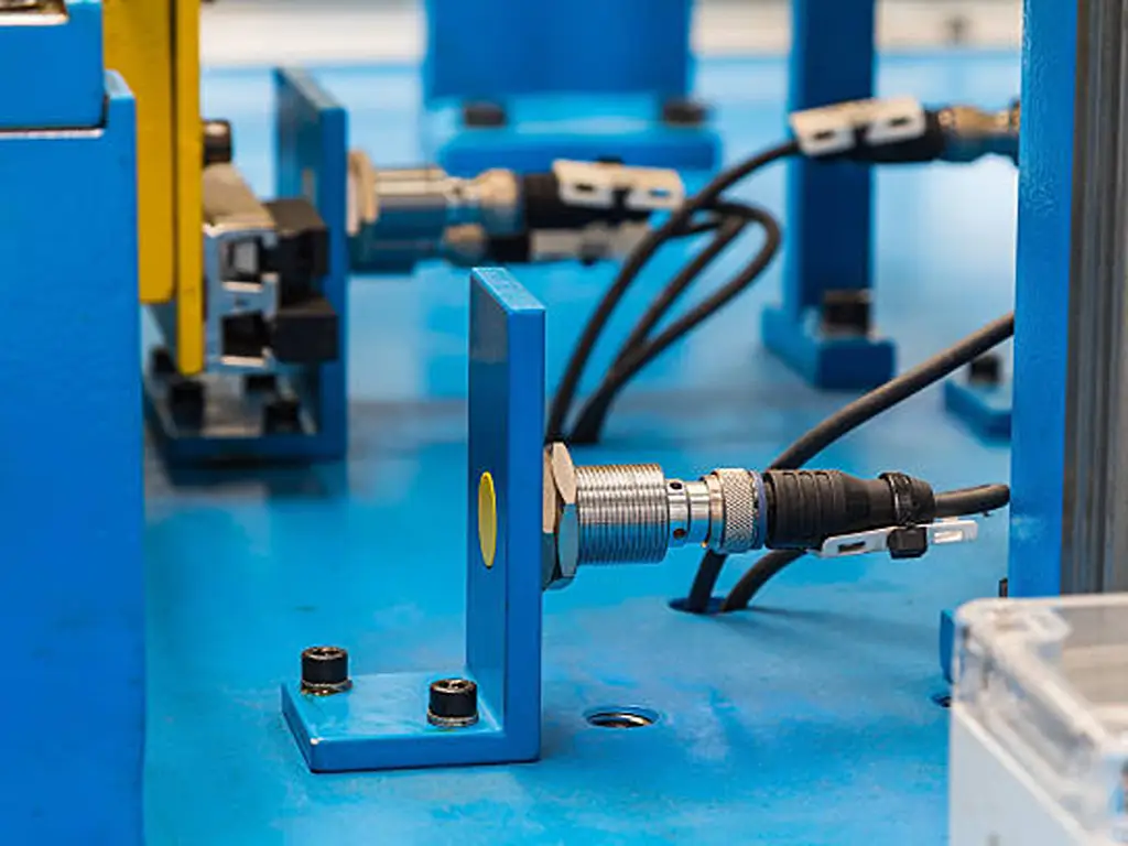
A yakınlık sensörü (aynı cihaz için “yakınlık anahtarı” da sıklıkla kullanılır) bağımsız ve temassızdır. Endüktif tipler yüksek frekanslı bir alan oluşturur ve bu alana metal girdiğinde devreyi açar; kapasitif tipler, farklı dielektrik sabitine sahip herhangi bir malzemeye tepki verir; fotoelektrik tipler ise ışığın kesilmesini veya yansımasını algılar. IEC 60947-5-2 standardına göre, bunlar yarı iletken anahtarlama elemanlarına sahip bağımsız cihazlar olarak tanımlanır. Bu nedenle bir güç kaynağına ihtiyaç duyarlar, düşük akımları anahtarlarlar ve — özel tipler satın almadığınız sürece — arıza koşullarında tanımlanmış bir arıza davranışı sergileyecek şekilde tasarlanmamıştır. Bu standart not önemlidir; nedenini güvenlik bölümünde göreceksiniz.
Bazen karşılaştığınız “yakınlık sınır anahtarı” terimi, üçüncü bir ürün kategorisi değildir. Bu terim, temassız hareket sonu algılama istediğinde kullanıcıların arama çubuğuna yazdıkları ifadedir: başka bir deyişle, sınır anahtarı işlevini yerine getiren bir yakınlık sensörü arıyorlar. Eğer aradığınız şey buysa, satın almadan önce algılama menzili bölümünü okuyun; çünkü bu iş, menzil ve montaj konusunda özel gereksinimler doğurur.
Her iki aile de aynı şeyi üretir: bir PLC girişi, bir röle veya bir sürücünün limit terminali için tek bir açık/kapalı sinyali. Aradaki fark, asla ne ürettiklerinde değildir. Fark, nasıl arızalandıklarında yatmaktadır ve bu, teknolojiden değil, kullanım koşullarınızdan kaynaklanır. Bu makale, işte bu eksen üzerine inşa edilmiştir.
Gerçek Spektrum: Aktüatörler, Algılama İlkeleri ve Aile Ağacının Önemi
Hiçbir aile tek bir ürün değildir. Dalları bilmek, yanlış iki öğeyi birbiriyle karşılaştırmanızı engeller.
Sınır anahtarları Çoğunlukla aktüatör başlığına göre sınıflandırılırlar; çünkü hangi durumun ve hangi yönden tetikleneceklerini belirleyen unsur başlıktır:
- Piston (pim): doğrudan dikey basınçla tetiklenir; kompakt ve hassastır, ancak makine parçasının pime dik bir şekilde oturması gerekir.
- Silindir piston / silindir kolu: Bir makara hareketli parça boyunca ilerler — kayar temas noktaları ve kamlar için en esnek seçenektir; kol tipi modeller ise çeşitli yönlerden yaklaşmaya izin verir.
- Çubuk / yaylı çubuk ve bıyık tipleri: Hafif bayraklar ve yavaş hareket eden parçalar için uzun stroklu veya düşük kuvvetli modeller.
- Çatal/çift devreli gövdeler: İçinde iki bağımsız kontak devresi bulunan (biri NO, biri NC) ağır hizmet tipi muhafazalar — güvenlikle ilgili kablolama için aradığınız konfigürasyon.
Yakınlık sensörleri algılama prensibine göre sınıflandırılırlar ve bu prensip, neyi algılayabileceklerini belirler:
| Mekanizma | Bunu tetikleyen nedir? | Aşağıdaki davranış |
|---|---|---|
| Tümevarımsal ⭐ (en yaygın olanı) | Salınım alanına giren metal | mm aralığında algılama; plastik, ahşap ve sıvıları algılamaz |
| Kapasitif | Yüzeyin yakınındaki dielektrikte meydana gelen herhangi bir değişiklik | Metal olmayan duvarların arkasını görebilir (seviye algılama, peletler, cam) |
| Fotoelektrik — ışın geçmeli / geri yansıtmalı / dağınık | Işık engellendi veya geri yansıtıldı | cm ila metre aralığı; temiz bir optik yol gerektirir |
| Manyetik (reed veya katı hal) | Yaklaşan bir mıknatıs | Demir içermeyen duvarların arkasından uzun menzilli; hareketli parçaya mıknatısın takılması gerekir |
Her ailenin uyması gereken davranış kuralı şudur: Bir indüktif sensör plastik paletinizi asla algılamaz, bir dağınık fotoelektrik sensör ışın yolundaki parlak yongalar nedeniyle yanlış tetiklenir ve bir mekanik başlık her zaman fiziksel temasa ihtiyaç duyar. Bu temas, bir nesnenin fiziksel olarak geldiğine dair kesin bir geri bildirim gerektiğinde tam da aradığınız özelliktir.
Başka yerlerde rastlayacağınız genel artı ve eksi listeleri genellikle tek boyutlu bir anlatıya indirgenir: “mekanik = ucuz, aşınır; yakınlık = aşınma yok, maliyeti daha yüksek.” Sıfatları bir kenara bırakırsak, mekanizmadan kaynaklanan iki gerçek fark kalır. Mekanik kontaklar fiziksel açık devrelerdir: hat geriliminde amper geçişi yapabilirler — kompakt limit anahtarları genellikle 250 VAC’de yaklaşık 5 A, ağır hizmet tipi kol anahtarları ise yaklaşık 10 A olarak derecelendirilir — ve kendilerine ait bir güç kaynağına ihtiyaç duymazlar. Yarı iletken çıkışlar, 10–30 VDC’de birkaç yüz miliamper geçişi yapar ve bu beslemenin mevcut olmasına ihtiyaç duyar. İnsanların “güvenilirlik” hakkında söyledikleri diğer her şey, cihazın bulunduğunuz ortamda farklı şekilde aşınmasına dair bir açıklamadır. Bu da bizi matrise getiriyor.
Sizin Koşullarınızda Hangisi İlk Önce Arıza Verir? Bir Arıza Sınırı Matrisi
Bu bölüm, makalenin asıl içeriğidir. Hangi teknolojinin “daha iyi” olduğu konusunu tartışmak yerine, gerçek bakım bütçelerini belirleyen şu soruyu yanıtlamaktadır: Benim çalışma koşullarımda hangisi önce arızalanır ve arızalandığında makine güvenli bir şekilde durur mu, yoksa öngörülemeyen davranışlar sergiler mi?
Kanıt temeli saha raporlarıdır, çünkü satıcı blogları bu konuda birbiriyle çelişmektedir. Eaton’ın bir sayfasında endüktif sensörlerin “kir ve yağa karşı dayanıklı” olduğu belirtilirken; Çinli bir sensör satıcısı, yakınlık sensörlerinin “yüksek sıcaklık, yüksek nem ve güçlü EMI” koşullarında performans kaybına uğradığını söyler; 2025’te yayınlanan bir panel atölyesi makalesi ise zorlu ortam konusundaki her iki görüşü de tek bir sayfada savunmayı başarır. Üçü de farklı açılardan haklıdır. Arıza matrisi bu açıları birbirinden ayırır.
Hata matrisi: altı durum × iki teknoloji
| Durum | Sınır anahtarı (mekanik) | Yakınlık sensörü (endüktif) | Kanıtların işaret ettiği yer |
|---|---|---|---|
| Yüksek döngü sayısı (>100.000 işlem/yıl) | Kontak ve mekanizma aşınması; arızalar genellikle açık ve ölçülebilir niteliktedir. Saha raporu: Bir demir dökümhanesinde anahtar başına yaklaşık 1 milyon döngü ≈ 6,5 ay. | Aşınacak hareketli parça yoktur. Saha raporu: Bir kum madeninde 20 yıl. | Yüksek çevrim sayısı → endüktif. |
| Toz, talaş, soğutma sıvısı, yağ | Sızdırmaz, ağır hizmet tipi üniteler doğrudan talaş maruziyetine dayanır (aktarım hattı raporu); kollarda yapışkanlık oluşabilir (ahşap reçinesi). | Temassız, sızdırmaz yüzey düz toprak zeminlerde daha iyi sonuç verir; yüzeydeki metal parçacıkları yanlış tetiklemeye neden olabilir. | Koruyucu kapaklı endüktif sensör — ya da etrafa saçılan talaşların bulunduğu ortamlarda fotoelektrik sensör. |
| Nem ve korozyon | Yaylar, bağlantı uçları ve kol pivotları korozyona uğrar — bu, uzak tesislerdeki klasik arıza türüdür. | Sızdırmaz elektronik bileşenler yıkamaya karşı dayanıklıdır; IP69K sınıfı üniteler neredeyse hiç bakım gerektirmez. | Bakım gereksinimi az olan ıslak ortamlar için endüktif. |
| Isı | Elektronik parça yoktur, ancak çalışma sıcaklığı yine de yaklaşık 70–85 °C ile sınırlıdır. | Tipik elektronik cihazların çalışma aralığı −25 ile +85 °C arasındadır. | Her halükarda teknik özellik belgesini kontrol edin; genelleme yapmayın. |
| Yüksek EMI (sürücüler, kaynak işlemleri, uzun kablo hatları) | Bir fiziksel temas, bir alan tarafından yanlışlıkla tetiklenemez. | Ekranlı kablolar ve EMC testi yapılmış (EN 60947-5-2) üniteler genellikle sorunsuz çalışır. | Kuru temaslar yalnızca koruma sağlanamayan hatlarda başarılı olur. |
| Darbe, forkliftler, hizasızlık | Kol kırılmış ya da gövde yerinden çıkmış. | Yüzeyi aşınmış ya da tamamen yerinden çıkmış. | Her ikisi de koruyuculara ve sağlam braketlere ihtiyaç duyar; ikisi de darbe aldığında hasar görür. |
Satırları bir skor tablosu olarak değil, koşullar olarak değerlendirin. En büyük ağırlığı iki saha raporu taşıyor. Bir demir dökümhanesini endüktif ünitelerle yenilemiş bir bakım mühendisi şöyle bildirdi (r/PLC alan başlığı, (2023) raporuna göre, yaklaşık 320 adet mekanik limit anahtarının her biri arızalanmadan önce yaklaşık bir milyon döngüye ulaştı — anahtar başına neredeyse tam olarak 6,5 ay — ve hat haftada iki ila üç kez duruyordu. Değişimden sonra, kendi ifadesiyle, “tüm limit anahtarı sorunlarımız ortadan kalktı.” Aynı mühendis, bir kum madeninde yirmi yıl boyunca çalışan endüktif yakınlık anahtarlarından da bahsetmiştir. Ancak aynı tartışma dizisindeki bir transfer hattı teknisyeni, mekanik anahtarların “bütün gün boyunca talaş ve soğutma sıvısıyla bombardımana tutulduğunu” bildirmiş ve bu anahtarları son derece sağlam olarak nitelemiştir. Aradaki farkı açıklayan şey şudur: Dökümhanedeki anahtarlar aşındırıcı toz içinde milyonlarca kez döngüye girerken; transfer hattındaki üniteler daha yavaş çalışır ve sızdırmazdır. Daha küçük atölyeler de aynı dengeyi minyatür ölçekte yaşar. Hobi amaçlı CNC üreticileri, referans noktası ayarlaması için yakınlık sensörlerinin daha tekrarlanabilir olduğunu fark eder; ancak sonra başıboş bir metal talaşı bir sensörü yanlış tetiklerken, kol anahtarları ise reçine içeriği yüksek ahşap işlerinde yapışıp kalır (r/hobbycnc başlığı, 2024).
Kullanım ömrü, teknolojiye değil, kullanım koşullarına bağlıdır. O tek cümle, herhangi bir teknik özellik tablosundan daha fazla argümanı açıklıyor.
Saha raporu: bir aile, iki hayat
1 milyon döngü ≈ 6,5 ay
Bir demir dökümhanesindeki mekanik limit anahtarları — endüktif yenileme çalışmasından önce bunların sayısı yaklaşık 320 idi
20 yılı aşkın
Bir kum madenindeki endüktif yakınlık sensörleri — aynı bakım mühendisi tarafından bildirildi
Aynı konum algılama ailesinden olsalar da, aralarında iki mertebe fark vardır. Kararı görev belirler — kutunun üzerindeki etiket değil.
Arıza güvenliği ilkesi: Bir cihazın nasıl arızalandığı, arızalanıp arızalanmadığından daha önemlidir
Mühendisler mekanik anahtarların “daha güvenli” olduğunu savunduklarında, genellikle kastettikleri şey, bir kontağın fiziksel olarak açık devre olmasıdır. Aşınmış bir kontak, kopmuş bir kablo, ezilmiş bir gövde: mekanik arıza türlerinin çoğu açık devre durumuyla sonuçlanır; bu durumda, doğru şekilde kablolanmış bir NC (normalde kapalı) devre, sessiz bir arıza yerine gözle görülür bir arızaya dönüşür. Yakınlık sensörlerinin arıza türleri ise tam tersi yöndedir: yanlış tetiklemeler, sensör yüzeyi ile hedef arasında kir biriktiğinde ortaya çıkan yanlış negatif sonuçlar ve algılama menzilindeki sapmalar. Bunların hiçbiri kendini belli etmez.
Bu asimetri, kablolama kurallarının teknoloji seçiminden daha önemli olmasının nedenidir. Aşağıdaki pratik kurallar, vinç ve konveyör koruması üzerine yapılan bir kontrol mühendisleri tartışmasından derlenmiştir (PLCTalk başlığı, 2017):
- Güvenlikle ilgili cihazı NO yerine NC olarak bağlayın. Bir vinç aşırı hareket kazasından sonra bir mühendisin genel kuralı: “Kablonun hasar görmesi veya fişinin çekilmesi durumunda da arıza vermesi için NC kullandık.” NO devresi sessizce arızalanır; NC devresi ise gürültülü bir şekilde arızalanır.
- Yedeklilik, ancak test prosedürünün kalitesi kadar etkilidir. Sapma kontrolü özelliğine sahip iki sensör, birbirlerinin sapmasını tespit edebilir — ancak bir mühendisin de belirttiği gibi, yedek sensörler ancak “sensörlerin çalıştığını düzenli olarak kontrol ederseniz” fayda sağlar.”
- “Arıza emniyetli” ibaresini tek başına bir gerekçe olarak kabul etmeyin. IEC 60947-5-2 standardı, sıradan yakınlık anahtarları için tanımlanmış arıza davranışını açıkça hariç tutmaktadır; arıza durumunda tanımlanmış davranışı garanti eden cihazlar, 60947-5-3 standardı kapsamındadır ve fiyatları da buna göre belirlenir. Bir makinenin güvenlik sınıflı bir durdurma işlevine ihtiyacı varsa, güvenlik sınıflı cihazı seçin. Temel ilke olarak, temaslı veya temassız cihazların “daha güvenli” olduğunu varsaymayın.
Bu kuralların ortaya çıktığı forum başlığı, yazarın son aşamada her iki tarafı da terk etmesiyle sona erdi: NC kablolamalı bir retroreflektif fotoelektrik sensör seçti; çünkü kendi ifadesiyle, bir limit anahtarı bükülerek konumundan sapabilir ve hedefi ıskalayabilir, bir yakınlık sensörü de bükülüp hedefi ıskalayabilir, ancak yerinden çıkan bir fotoelektrik sensör veya reflektör anında devreye girer. Buradan çıkarılacak ders, “fotoelektrik sensör en iyisidir” değildir. Buradan çıkarılacak ders, arızanın tespit edilebilirliğinin sizin seçtiğiniz bir tasarım özelliği olduğudur ve bu özellik, her türlü güvenlik tartışmasında “temaslı mı, temassız mı” tartışmasından daha önceliklidir.
Her ikisi de tek bir makineye aittir: sistem rollerinin nasıl bölündüğü
“Sınır anahtarı mı, yoksa yakınlık sensörü mü?” sorusu, sessizce bunlardan birini seçmeniz gerektiğini varsayar. Gerçek makinelerde durum böyle değildir. Yolcu ve yük asansörleri her ikisini de barındırır: uçlarda aşırı hareketi önleyen mekanik limit anahtarları, her katta durma konumunu belirleyen yakınlık veya diğer sensörler — bir gemide iki kargo vinci çalıştıran bir gemi mühendisi, bu ayrımı tam olarak böyle tanımlamıştır. Bir kaldırma uygulamasında, kablolama hedefine göre bu sensörler katmanlara ayrılmıştır: kontrol mantığı için PLC’ye yakınlık sensörü, sert durdurma için ise servo sürücünün limit girişlerine doğrudan mekanik NC kontakları bağlanmıştır.
Temassız sistem, sık yapılan işleri halleder
Konumlandırma ve referans noktasına dönüş için endüktif veya fotoelektrik sistemler — döngü sayısı yüksek olduğunda sıfır aşınma.
"Mekanik (veya NC kablolu)" seçeneği son satırı korur
Aşırı hareket durumunda tespit edilebilir bir açık konum, uzun ömürden daha değerlidir — işte güvenlikle ilgili tercih budur, marka sadakati değil.
Yeni makine tasarımları, konum algılama işlerini temassız cihazlara kaydırmaya devam ederken, yedek parça pazarı ise mevcut kurulu sistemler için mekanik üniteleri satın almaya devam ediyor — işte bu nedenle her iki ürün grubu da yüksek satış hacimleri kaydetmeye devam ediyor. Bu bir arada var olma durumu bir geçiş dönemi değil; bir iş bölümü niteliğindedir.
Karar ister temassız ister mekanik olsun, değiştirme işlemi dört temel unsuru içerir — montaj, güç, mantık devresi, yük — ve bu dört unsuru da karşılayan tedarikçi, iletişime geçmeye değer olan tedarikçidir.
Değiştireceğiniz ürünü ürün yelpazemizle karşılaştırınYedek Parça Seçimi: Algılama Mesafesi, Çıkış Kablolaması ve Dört Noktalı Kontrol
Karar verildikten sonra, hataların çoğu sipariş aşamasında ortaya çıkar. Sipariş formunda en sık görülen iki hata — yanlış algılama aralığı ve yanlış çıkış türü — her ikisi de bu bölümde açıklığa kavuşturulan bir yanlış anlamadan kaynaklanmaktadır.
Algılama mesafesi, gövde boyutuna bağlıdır — pazarlama stratejisine değil
Her yerde rastlayacağınız forum tartışması — “yakınlık sensörleri sadece 2–3 mm algılar, işe yaramazlar” ile “10 mm normaldir” — bir tartışma konusu değildir. Bu, iki farklı gövde sınıfının tek bir ürünmüş gibi karşılaştırılmasıdır. Endüktif algılama mesafesi, algılama kafasının çapına ve kafanın korumalı (gömme montajlı) mı yoksa korumasız mı (ön yüzünün çevresinde metal içermeyen bir bölge gerektirir) olduğuna bağlı olarak değişir. Çelik bir hedef üzerinde DC endüktif sensörler için tipik menziller:
Gövde boyutuna göre tipik endüktif algılama mesafeleri (çelik hedef, temsili DC tipleri)
| Konut | Düz / ekranlı | Gömme olmayan / ekranlanmamış |
|---|---|---|
| M8 | 1,5–2 mm | ≈2 mm |
| M12 | 2–3 mm | 4–8 mm |
| M18 | 5–7 mm | 8–14 mm |
| M30 | ≈10 mm | 15–20 mm |
| Fotoelektrik (herhangi bir gövde) | yok | santimetre – metre dönüştürme |
“2–3 mm işe yaramaz” argümanı genellikle elinde M8 veya M12 gömme tip bir ünite olan kişilerden gelir; “10 mm yeterlidir” cevabı ise M30 korumasız bir üniteye aittir. Her ikisi de kendi muhafazaları hakkında doğru bilgi vermektedir. OMRON’un E2E serisi, tam olarak bu skalayı yansıtmaktadır — 2–3 mm’de ekranlı M12, 18–20 mm’de ekranlı olmayan M30 — ve SICK’in IME veri sayfası, 4 mm’de bir M12 gömme olmayan ünitenin varlığını doğrulamaktadır. Toleranslar ±10% aralığındadır ve her üreticinin serisi farklılık gösterir; bu nedenle, satın aldığınız ürünün veri sayfasında belirtilen değer, dikkate alınması gereken tek değerdir.
Üç temel kural, yıllarca sorunsuz çalışan bir sensör ile sürekli servis çağrılarına neden olan bir sensör arasındaki farkı belirler:
- Hedef malzeme, menzili azaltır. Katalogdaki mesafeler yumuşak çelik üzerinde ölçülmüştür. Gerçek koşullara göre düzeltme katsayıları: paslanmaz çelik ≈0,8, alüminyum ≈0,3–0,45, bakır ≈0,25–0,45. Alüminyum bir bayrağa yöneltilmiş 4 mm’lik bir M12 sensör, fiilen ~1,5 mm’lik bir sensör gibidir.
- Korumasız başlıkların serbest metal alanı olması gerekir. Ekransız bir ünitenin daha uzun menzili, onu çelik bir braketin içine gömerseniz kaybolur; üreticiler, ön yüzün çevresinde metal bulunmayan bir bölge belirler (genellikle nominal mesafenin 2–3 katı kadardır — veri sayfasındaki montaj notuna bakınız) ve ekransız sensörlerin montaj yüzeyinden dışarı çıkması gerekir.
- Yüz ile hedef arasında hiçbir engel bulunmayacak bir yere monte edin. Bir bakım mühendisinin yanlış negatif sonuçlara ilişkin analiz raporu: Kapak ile algılama yüzeyi arasına sıkışan malzeme, uzak bir tesiste hayali servis çağrılarına neden oldu. Algılama yüzeyine engelsiz bir görüş açısı sağlayın ve gerçek tetikleme mesafesine göre nominal menzilin en az 1,5–2 katı kadar bir pay bırakın.
Çıkışlar ve kablolama: kuru kontaklar ve yarı iletken anahtarlar
Bu, en sık görülen ikinci sipariş hatasıdır ve teslimat aşamasında değil, devreye alma aşamasında sorun çıkaran hatadır. Mekanik limit anahtarlarının çıkışı kuru kontaklar: NO/NC/SPDT metal kontaklar, amper cinsinden nominal değerlidir (kompakt üniteler için tipik değer 250 VAC’de 5 A; ağır hizmet tipi kol modelleri için 10 A sınıfı), kutuplama gerektirmez, güç kaynağı gerektirmez, kontaktör bobinine veya lamba devresine doğrudan bağlanabilir. Yakınlık sensörleri çıkışı yarı iletken anahtarlar 10–30 VDC gerektiren ve en fazla birkaç yüz miliamper anahtarlama yapanlar — örneğin, SICK’in IME12 veri sayfasında sürekli akım değeri ≤200 mA olarak belirtilmiştir. Ayrıca polarite seçenekleri de mevcuttur: PNP (tedarik) açık durumdayken +24 V çıkış verir — Avrupa ve Asya’da PLC girişleri için yaygın olarak tercih edilen seçenek — ve NPN (verici) 0 V’a düşer; bu, Asya’nın bazı bölgelerinde ve bazı eski kartlarda yaygın olarak kullanılır. Yenileme işlemlerini kolaylaştırmak ve AC paneller için iki telli DC ve iki telli AC versiyonları mevcuttur.
Sahada gerçekten yaşanan kablolama hataları: NPN birimini PNP girişi bekleyen bir PLC girişine bağlamak (kanal asla açılmaz), bir sensör çıkışının eskiden sürücü olarak kullanılan bir kontağı sürülebileceğini varsaymak (sürülemez — ara röle ekleyin) ve bir güvenlik fonksiyonu için NO’yu seçmek (güvenli arıza bölümüne bakın). Aynı devre sembolü mantığının her iki aile için de geçerli olduğuna dikkat edin: şemada bir kontak olarak çizilen bir yakınlık “anahtarı”, fiziksel bir kontak olmasa bile yine de NO/NC mantığına uyar.
Dört maddelik yedek parça kontrolü
Arızalı bir üniteyi değiştirirken — ya da bir müşteri sizden aynı ürünü temin etmenizi istediğinde — sipariş vermeden önce bu dört maddeyi gözden geçirin. Atlanan her madde, bilinen bir arıza türüdür:
- Montaj arayüzü. Diş/gövde çapı (M8/M12/M18/M30), gövde tipi ve mekanik ünitelerde aktüatör başlığı: makara yönü, ön hareket mesafesi ve aşırı hareket mesafesi. Bu ayarlar yanlış yapılırsa, ünite ya hiç tetiklenmez ya da sürekli sıkıştırılmış halde kalır.
- Güç. Eski ünite kuru kontak mıydı (güç kaynağı gerektirmeyen) yoksa güç beslemeli bir sensör müydü? Panelinizde o noktada 10–30 VDC voltaj yoksa, yarı iletken bir yedek parça kullanılması işe yaramaz.
- Mantıklı. NO veya NC; yarı iletken türleri için ise PNP veya NPN. Bir güvenlik devresinde ters çevrilmiş bir NC/NO, bir kazanın yaşanmasını bekleyen sessiz bir arızadır.
- Yükle. Çıkış aslında neyi çalıştırıyor? Kontaktör bobinini doğrudan besleyen 5 A’lık bir kontağın yerine 200 mA’lık bir sensör çıkışı kullanılırsa, bu sistem arızalanacaktır — genellikle de en kötü anda.
Ayrıca, modernizasyon sadece donanımla ilgili değildir. O dökümhane mühendisinin fabrikası endüktif ünitelere geçtiğinde, ilk arızalar “teknisyenlere, endüktif yakınlık anahtarını tetiklemek için ona VURMAMALARI gerektiğini öğretmek”ten kaynaklandı — yıllarca limit anahtarı kollarına sertçe vuran teknisyenler, yeni sensörleri fiziksel olarak kırıyorlardı. Tetikleme alışkanlığını yeniden eğitmeyen bir modernizasyon, eski arıza türlerini de beraberinde getirir.
Bir Konum Anahtarı “Arızalandığında”: Önce Arıza Teşhisi, Sonra Yenileme
Bir makine durur, alarm anahtarı gösterir ve ilk akla gelen şey parçayı değiştirmektir.
Parçayı ancak kablolama, tetik ve montajın hepsinin sorunsuz çalıştığı test edildikten sonra değiştirin — en sık değiştirilen sensörler nadiren arızalı olanlardır.
Beş adımda teşhis:
- Kilitleme ve izole etme devre.
- Öncelikle kablolamayı ve girişi kontrol edin. PLC/kart tarafında ölçüm cihazının devre bütünlüğü ve gerilim. Kopmuş veya ezilmiş bir kablo, arızalı bir cihazla tam olarak aynı belirtileri gösterir; ayrıca NC kablolamada, bir kablo arızası tasarım gereği görünür bir alarm olarak ortaya çıkar.
- Cihazı elle çalıştırın. Aktüatörü manuel olarak çalıştırın veya hedefi algılama yüzeyine getirin. Göstergeyi ve giriş durumundaki değişikliği izleyin.
- Üç şüpheliyi birbirinden ayırın: cihaz arızası, kablolama/konektör arızası veya montajın yerinden oynaması (bükülmüş braket, kaymış hedef, boşluktaki kirlenme). Konum algılama sorunlarına ilişkin saha arıza analizleri sürekli aynı sonuca varıyor: mekanik anahtarlar, mekanizmaların aşınması nedeniyle bozuluyor, yakınlık sensörlerinin yüzeyleri aşınıyor ve her ikisi de düşen nesnelerin kabloyu koparması sonucu devre dışı kalıyor — “kırık limit anahtarı kolu mekanik bir sorundur; kopan kablolar ise düşen bir nesneye bağlıdır” (PLCTalk tartışması, 2013). Aslında arıza veren mekanizmayı suçlayın.
- Ancak o zaman sipariş verin. Siparişinizi, yukarıdaki dört maddelik kontrol listesine göre verin; “orijinal makinedeki aynı parça numarası”na göre değil, çünkü o parça numarası artık mevcut olmayabilir ya da kablolama düzeninden farklı bir mantık varyantı olabilir.
Değiştirme işleminden sonra, eski arıza türlerini değil, yeni arıza türlerini göz önünde bulundurun. Servis kayıtlarında en çabuk arızalanan cihazlar, darbelere maruz kalan yerlere monte edilmiş, esneyen braketlere takılmış ve kabloları sürtünmeye maruz kalan cihazlardır. Bunları koruyun, sabitleyin ve gerilimi azaltın — bu, markadan daha önemlidir.
Yedek parça stok hesaplamaları, bu makaledeki diğer her şey ile aynı koşul mantığını izler. Dökümhane raporunda, bir milyon döngü 6,5 aya denk geliyordu — bu iş yükünde çalışan bir tesisin, mağazaya acil bir şekilde gitmek yerine, rafta hazır yedek parçalara ve planlı bir değiştirme sıklığına ihtiyacı vardır. Yavaş ve temiz çalışan bir makinede aynı parça grubu, makinenin ömrünü bile aşabilir. Yedek parçaları, tedarikçinin genel “uzun ömür” iddiasına göre değil, kendi döngü sayınıza ve kirlilik seviyenize göre stoklayın — CMMS sisteminizin zaten bildiği rakamlara göre. Bu çalışma mantığı, eski bir mühendislik uygulamasıdır: Çok yüksek döngülü test tezgahları inşa eden mühendisler, on yıllardır temassız algılama yöntemini tercih etmişlerdir; çünkü bu yöntem, aşınmayı denklemden tamamen ortadan kaldırır (eng-tips başlığı, 2002).
Değiştirilen cihaz bir güvenlik işlevi görüyorsa, devrenin incelenmesini sağlayın. NC kablolaması, yedeklilik kontrol rutini ve güvenlik sertifikalı cihaz seçimi, “değiştir ve kullan” tarzı bir modernizasyonun garanti ettiği hususlar değildir.
Bayiler için: İki Ürün Grubu, Tek Tezgah — Yedek Stok Mantığı
Otomasyon bileşenleri dağıtımı yapıyorsanız, yukarıda belirtilen her şey üç iş gerçeğine indirgenir. Birincisi: Makineler tasarım gereği her iki ürün grubunu da barındırır — asansörler, vinçler, konveyörler ve takım tezgahları, mekanik sınırlayıcıları ve yakınlık sensörlerini farklı rollerle bir araya getirir — dolayısıyla, tek bir ürün grubunu stoklayan bir distribütör, kendi pazarındaki yedek parça siparişlerinin yarısını yapısal olarak gözden kaçırır. İkincisi: yedekleme sıklığı, müşterinin çalışma yüküne bağlıdır ve iki kat farklılık gösterebilir — bir fabrikada 6,5 ayda bir bozulan aynı anahtar ailesi, başka bir fabrikada yirmi yıl dayanabilir — bu da stok derinliğinin, kategori ortalamasına değil, müşterilerinizin gerçek döngü sayılarına göre belirlenmesi gerektiği anlamına gelir. Üçüncüsü: Yedek siparişleri neredeyse hiçbir zaman ’bana bir yakınlık sensörü sat“ şeklinde gelmez. ”X makinesi için bir parçaya ihtiyacım var“ şeklinde gelir — ve siparişin kazanılıp kazanılmayacağı, dört maddelik kontrol listesine (montaj, güç, mantık, çıkış) cevap verebilmenize bağlıdır.
Asıl değer işte bu üçüncü noktada yatmaktadır. Onarım ve bakım pazarı, makinenin orijinal parça numarasına göre satın alma yapar; orijinal parça bulunmadığında ise, satış, bu dört noktayı karşılayan uyumlu bir yedek parça sunabilen — ve ne zaman zorlamaması gerektiğini bilen — tedarikçiye gider. Dört noktalı kontrolü dürüstçe karşılayan bir tedarikçi, bir $12 anahtarını on yıllık yeniden stok siparişlerine dönüştüren güveni oluşturur. Bunu pratik kılan ürün yelpazesi, tek noktadan hizmet sunan bir kataloğun amacıdır. OMCH’de her iki ürün grubu da yan yana yer almaktadır: limit anahtarı yelpazemiz, kompakt 5 A’lık ünitelerden, 250 VAC’de 10 A nominal değerine sahip, 500.000’den fazla çalışma ömrü sunan ağır hizmet tipi kol anahtarlarına kadar uzanır ve yakınlık anahtarı ve sensör ürün yelpazemiz M8’den M30 sınıfına kadar gövdeli endüktif yakınlık sensörlerini — 1–2 mm’den 10–15 mm’ye kadar nominal mesafe, IP67, −30 ila +85 °C, NPN, PNP, iki telli DC ve AC versiyonlarında — fotoelektrik ve kapasitif ürün gruplarının yanı sıra kapsamaktadır. 30'dan fazla kategori ve 3.000'den fazla SKU'yu içeren bir katalogda, limit anahtarı ve yakınlık sensörü asla birbirinin yerine geçecek seçenekler değildir; bunlar, aynı dört maddelik kontrol listesiyle eşleşen, aynı tezgâhta sunulan iki çözümdür. Eğer bir yedek parça gerçekten uymuyorsa — yanlış montaj, yanlış mantık, sertifikalandıramayacağımız bir güvenlik sınıfı gereksinimi — size bunu söyleyeceğiz; çünkü yanlış bir parçanın iadesi, dürüstçe "hayır" demekten daha pahalıya mal olur.
Her iki ürün grubunu da stoklayın, müşterilerinize “dört maddelik dil”i öğretin; böylece “sınır anahtarı mı, yakınlık sensörü mü” sorusu, müşterilerinizin size yönelttiği bir tartışma konusu olmaktan çıkacak — aksine, sizi ilk aramalarının nedeni haline gelecektir. Ekibimizle görüşün ürün yelpazesi hakkında bilgi edinin veya limit anahtarı ve yakınlık sensörü katalogları inceleyin ve kendi yedek parça listenizi bu kontrol sürecinden geçirin.
Her İki Hattı da Stokunuza Dahil Edin — Limit ve Proximity için Distribütör Koşulları
Tam limit anahtarı (AZ/TZ) ve endüktif yakınlık sensörü (AL-J) serileri, teknik özellik belgeleri, makineye özgü parça numaraları için çapraz referans yardımı ve her teklifte yapılan dört maddelik kontrol.
Bayi fiyatlarını talep etKaynakça
-
CSA Group / Kanada Standartlar Konseyi. “CAN/CSA-C22.2 No. 60947-5-1 — Alçak Gerilim Şalt ve Kontrol Cihazları, Bölüm 5-1: Kontrol Devresi Cihazları ve Anahtarlama Elemanları.” 17 Ekim 2018.
https://scc-ccn.ca/standards/notices-of-intent/csa-group/low-voltage-switchgear-and-controlgear-part-5-1-control -
CSA Group / Kanada Standartlar Konseyi. “CAN/CSA-C22.2 No. 60947-5-2 — Bölüm 5-2: Kontrol Devresi Cihazları ve Anahtarlama Elemanları, Yakınlık Anahtarları.” 7 Ağustos 2026.
https://scc-ccn.ca/standards/notices-of-intent/csa-group/low-voltage-switchgear-and-controlgear-part-5-2-control-2 -
OMRON Endüstriyel Otomasyon. “E2E Serisi Ürün Yelpazesi — Standart Silindirik Endüktif Yakınlık Sensörleri.” 11 Kasım 2024.
https://www.ia.omron.com/products/family/449/lineup.html -
SICK AG. “IME12-04NPSZW5K Teknik Özellik Sayfası — Endüktif Yakınlık Sensörü, M12, Gömme Olmayan, Sn 4 mm, PNP NO, 10–30 VDC, ≤200 mA, IP67.” PDF.
https://www.sick.com/media/pdf/0/60/460/dataSheet_IME12-04NPSZW5K_1042725_en.pdf -
SICK AG. “Endüktif Sensörler — Çalışma Prensibi, Montaj ve Uygulama.” 24 Şubat 2022.
https://www.sick.com/at/en/inductive-sensors-function-mounting-and-application/w/blog-induktiver%20sensor -
Balluff. “Endüktif Yakınlık Sensörü Hedef Malzemesi: Önemli mi?” 18 Haziran 2024.
https://www.balluff.com/en-us/blog/inductive-proximity-sensor-targets-material-does-matter -
wenglor sensoric group. “Gömme Olmayan Montaj — Teknik Terimler Sözlüğü.”
https://www.wenglor.com/en/Non-Flush-Mounting/l/cxmCID73182 -
Reddit r/PLC. “Bu Mekanik Limit Anahtarlarını Endüktif Olanlarla Değiştirmeyi Düşünüyorum.” 28 Ekim 2023. Saha raporları.
https://www.reddit.com/r/PLC/comments/17i270n/thinking_of_replacing_these_mechanical_limit/ -
PLCTalk. “Yakınlık Sensörleri ve Mekanik Limit Anahtarları Karşılaştırması.” 2017. Vinç aşırı hareket katmanlaması, NC kablolama kuralı ve fotoelektrik nihai çözüm raporu.
https://www.plctalk.net/forums/threads/proximity-vrs-mechanical-limit-switches.108892/ -
PLCTalk. “Hiç Fikrin Olmadığı İşlerle Başa Çıkmak.” 2013. Konum algılama arızalarının nedenleri: aşınmış mekanizmalar, aşınmış yüzeyler ve kopmuş kablolar.
https://www.plctalk.net/forums/threads/dealing-with-jobs-you-have-no-clue-of.79012/ -
Eng-Tips. “Yakınlık Sensörü ve Mekanik Limit Anahtarı.” 2002. Yüksek döngü sayısına uygun seçim mantığı.
https://www.eng-tips.com/threads/proximity-sensor-vs-mechanical-limit-switch.19201/ -
Reddit r/hobbycnc. “Yakınlık Anahtarları ve Limit Anahtarları.” 21 Ocak 2024. Tekrarlanabilirlik ile yonga kaynaklı yanlış tetikleme arasındaki ödünleşimler.
https://www.reddit.com/r/hobbycnc/comments/19c80r2/proximity_switches_vs_limit_switches/



 English
  Arabic
  Turkish
  Russian
  Spanish
  French
  Indonesian
  Portuguese
  Thai
Thai  Vietnamese