












Doğrusal Güç Kaynağı Nedir?
Doğrusal güç kaynağı, bir düşürme transformatörü ve bir doğrusal gerilim regülatörü (aktif bölgesinde çalışan ve hassas bir çıkış gerilimini korumak için sürekli ayarlanabilir bir direnç gibi davranan bir transistör) kullanarak alternatif akım şebeke elektriğini sabit, düşük gürültülü bir doğru akım çıkışına dönüştüren bir tür doğru akım güç kaynağıdır.
Bunu titiz bir zanaatkar gibi düşünün: gereğinden fazla enerji harcar, ancak sonuç olağanüstü derecede temizdir. Doğrusal güç kaynakları genellikle 40% ile 60% arasında bir verimlilik gösterir — bu da giriş gücünün neredeyse yarısının, yararlı çıkış yerine ısıya dönüştürülebileceği anlamına gelir (Acopian). Buna karşılık, 0,25 mV RMS kadar düşük bir çıkış dalgalanması üretirler — bu, tipik bir anahtarlamalı güç kaynağına kıyasla 20 ila 50 kat daha düşük bir seviyedir.
Ağırdırlar, fazla ısınırlar ve tasarımları on yıllardır neredeyse hiç değişmemiştir. Yine de laboratuvarlarda, kayıt stüdyolarında, hastanelerde ve tamamen temiz DC güç gerektiren her yerde, doğrusal güç kaynakları hâlâ vazgeçilmezdir. Bunun nedenini anlamak için nasıl çalıştıklarını görmeniz gerekir.
Doğrusal Güç Kaynağı Nasıl Çalışır?
Her lineer güç kaynağı, aynı dört aşamalı sinyal yolunu izler: AC şebeke akımı girer, gerilimi düşürülür, doğrultulur ve filtrelenerek kaba DC haline getirilir; son olarak da bir lineer regülatör tarafından işlenerek temiz ve kararlı bir çıkış elde edilir. Bu süreç dört aşamadan geçer.
1. Adım — Transformatör: Gerilimi Düşürme
AC şebeke akımının karşılaştığı ilk şey, büyük bir demir çekirdekli transformatördür. Görevi oldukça basittir: Duvardan gelen 110 V veya 220 V’luk akımı alır ve bunu çok daha düşük bir AC gerilime düşürür — genellikle ikincil tarafta 12 V ile 24 V AC arasında bir değere. Ayrıca, güvenlik amacıyla devrenizi şebekeden ayırarak galvanik izolasyon sağlar.
Bu transformatör, lineer güç kaynaklarının bu kadar büyük ve ağır olmasının en önemli nedenidir. Şebeke frekansı olan 50 veya 60 Hz’de çalışır ve bu düşük frekanslarda verimli bir transformatörün oldukça büyük bir demir çekirdeğe ve çok sayıda bakır tel sargısına ihtiyacı vardır. 100 watt’lık bir lineer güç kaynağının sadece transformatörü 1,5 ila 2,5 kilogram ağırlığında olabilir.
Bunu, transformatörün 50 kHz veya daha yüksek frekansta çalıştığı bir anahtarlamalı güç kaynağıyla karşılaştırın: frekans arttıkça gerekli manyetik kesit küçüldüğü için çekirdek, orijinal boyutunun çok küçük bir kısmına indirgenir. Ancak doğrusal bir tasarımda, bu hacimden kaçınmak mümkün değildir — bu, basitliğin bedelidir.
2. ve 3. Adım — Doğrultma ve Filtreleme: Alternatif Akımdan Kaba Doğru Akıma
Transformatör düşük gerilimli alternatif akım sağladıktan sonra, bir köprü redresör — elmas şeklinde düzenlenmiş dört diyot — her alternatif akım döngüsünün negatif yarısını yukarı doğru çevirerek, alternatif sinüs dalgasını bir dizi pozitif yönlü tepe noktasına dönüştürür. Mühendisler buna “titreşimli doğru akım” adını verir.”
Bu bir başlangıçtır, ancak kullanışlı bir sonuç değildir. Gerilim hâlâ saniyede 100 veya 120 kez sıfırdan tepe değerine salınmaktadır (döngünün her iki yarısı da artık aynı yöne baktığı için bu, şebeke frekansının iki katıdır). Bunu düzeltmek için, doğrultucu çıkışına büyük bir elektrolitik kondansatör — genellikle birkaç bin mikrofarad, örneğin 4.700 µF veya 10.000 µF — bağlanır. Bu depo kondansatörü, her tepe noktasında tepe gerilime kadar şarj olur ve tepe noktaları arasındaki boşluklarda yüke deşarj olur; böylece dalga formunu DC'ye benzeyen bir şekle getirir, ancak yine de dalgalanma içerir.
Yararlı bir zihinsel model: Kondansatör, bir su deposu gibi davranır. Kaynak tarafında, redresör suyu darbeler halinde besler. Yük tarafında ise yük sürekli olarak su çeker. Depo, ani akım artışlarını emerek sabit bir akış sağlar — ancak yüzeyde yine de dalgalanmalar görülür.
4. Adım — Gerilim Düzenlemesi: Doğrusal Tasarımın Kalbi
İşte bu noktada doğrusal güç kaynakları adını hak eder. Kaba bir şekilde filtrelenmiş doğru akım, şimdi doğrusal veya aktif bölgesinde çalışan bir seri geçiş transistörüne — yani düzenleme elemanına — girer. Tamamen açık ya da tamamen kapalı konumlara sahip bir anahtarın aksine, bu transistör her zaman kısmen açıktır ve değişken bir direnç gibi davranır.
Bir geri besleme devresi, çıkış gerilimini sürekli olarak izler. Gerçek çıkışı, hassas bir referans gerilimle (genellikle ±2% ile ±5% arasında bir doğrulukta) karşılaştırır ve transistörün direncini dinamik olarak ayarlar: çıkış çok yükselirse, transistör kendi üzerinden daha fazla gerilim düşmesi için direncini artırır; çok düşerse ise direncini azaltır. Sonuç olarak, giriş gerilimi veya yük akımındaki değişikliklerden bağımsız olarak son derece kararlı bir çıkış elde edilir.
Bu ödünleşim, tek bir denklemle ifade edilebilir:
P_dissipated = (V_in − V_out) × I_load
Gerçek bir örnek ele alalım: Girişinden 18 V alan ve yüke 2 A akımla 12 V veren bir doğrusal regülatör. Transistördeki voltaj düşüşü 6V'tur ve üzerinden 2A akım geçtiğinde bu, 12 watt ısı anlamına gelir — tamamen israf olan ve bir soğutucu tarafından uzaklaştırılan enerji. Bu nedenle lineer güç kaynakları ısınır ve verimlilikleri temel olarak sınırlıdır: giriş ve çıkış voltajı arasındaki fark ne kadar büyükse, o kadar fazla enerji ısıya dönüşür.
LM317 (ayarlanabilir) ve 78xx sabit gerilim serisi (5 V için 7805, 12 V için 7812) gibi klasik entegre doğrusal regülatörler, bu geri besleme ve düzenleme devresinin tamamını tek bir üç pimli yongaya sığdırır. Bu devreler, kırk yılı aşkın bir süredir elektronik tasarımının vazgeçilmez unsurları olmuştur — basittir, güvenilirdir ve yeterli soğutma sağlandığında bozulmaları neredeyse imkânsızdır.
AC gerilimini düşürür
AC kaba DC
Hassas gerilim kontrolü
<1 mV dalgalanma
Doğrusal ve Anahtarlamalı Güç Kaynakları: Temel Farklılıklar
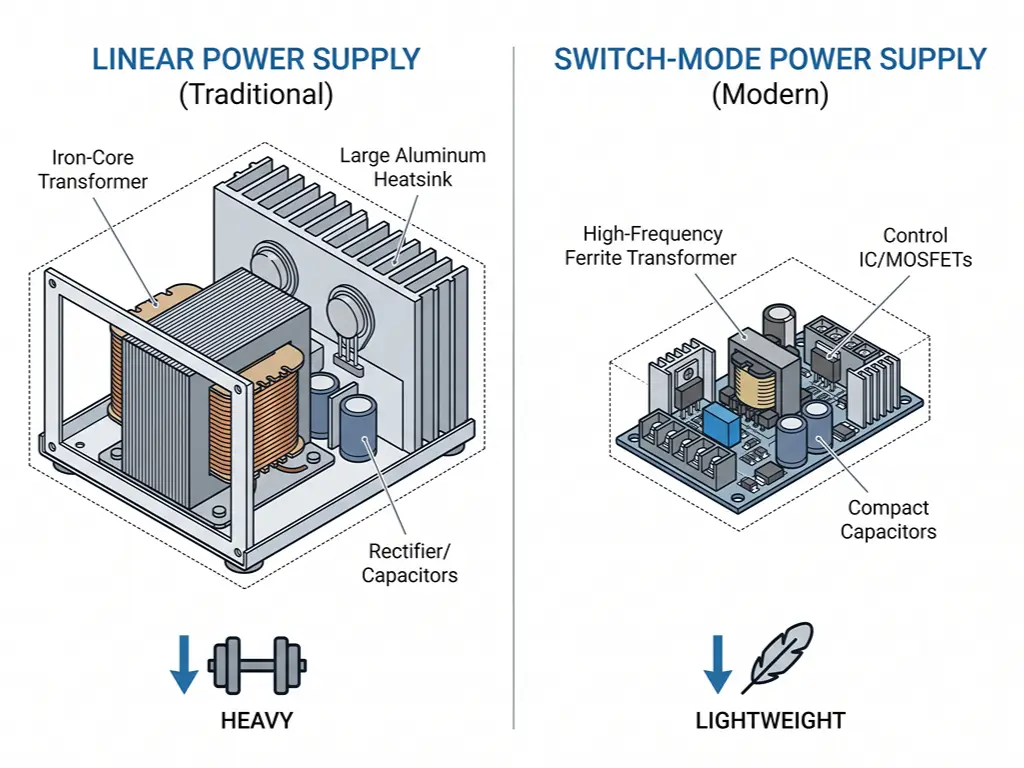
Güç elektroniği alanında biraz zaman geçirdiyseniz, şu tartışmayı duymuşsunuzdur: doğrusal mı, yoksa anahtarlamalı mı? Aşağıdaki karşılaştırma tablosu, rakamları bir bakışta gözünüzün önüne seriyor. Ancak bağlamından kopuk rakamlar yanıltıcı olabilir — bu nedenle her bir boyut aşağıda ayrıntılı olarak ele alınmaktadır.
| Boyut | Doğrusal Güç Kaynağı | Anahtarlamalı Güç Kaynağı (SMPS) |
|---|---|---|
| Verimlilik | Kırk ila altmış bir bin üç yüz otuz üç | 70–90%+ |
| Çıkış Dalgalanması (RMS) | 0,25–1,5 mV | 10–25 mV |
| Boyut ve Ağırlık | Büyük, ağır | Kompakt, hafif |
| Devre Karmaşıklığı | Basit | Karmaşık |
| Elektromanyetik parazit / Radyo frekansı paraziti | Çok düşük | Yüksek — ekranlama gerektirir |
| Geçici İyileşme | 50–100 µs | ~300 µs |
| Yük Regülasyonu | 0,005–0,21 TP3T | 0,05–0,51 TP3T |
Kaynak: Acopian Güç Kaynakları Karşılaştırması
Verimlilik ve Isı — Temel İkilem
Doğrusal ve anahtarlamalı güç kaynakları arasındaki verimlilik farkı, mühendisliksel bir iyileştirme meselesi değildir — bu fark, bunların çalışma prensiplerinin doğasında yatmaktadır.
Doğrusal bir güç kaynağında, seri bağlı geçiş transistörü her zaman iletken durumdadır, her zaman voltaj düşüşüne neden olur ve her zaman güç tüketir. Yüke iletilmeyen her watt ısıya dönüşür. Giriş-çıkış voltaj farkı büyük olduğunda verimlilik önemli ölçüde düşer: 18V girişten elde edilen 5V çıkış, giriş gücünün 70%’sinden fazlasını ısı olarak boşa harcar.
Bir anahtarlamalı güç kaynağı bu sorunu tamamen ortadan kaldırır. Bu güç kaynağındaki transistör — genellikle bir MOSFET — yalnızca iki durumda çalışır: tamamen açık (üzerindeki gerilim sıfıra yakın olduğu durumda) veya tamamen kapalı (içinden geçen akım sıfıra yakın olduğu durumda). Her iki durumda da, gerilim ve akımın çarpımı — yani güç kaybı — ihmal edilebilir düzeydedir. Kayıplar yalnızca kısa anahtarlama geçişleri sırasında meydana gelir ve 50 kHz ile 1 MHz arasındaki anahtarlama frekanslarında, tek haneli miliohm seviyesinde açma direncine sahip modern MOSFET'ler bu kayıpları oldukça düşük tutar. Sonuç olarak: 100 W'lık bir anahtarlamalı güç kaynağı 10 ila 15 watt'ı ısı olarak israf ederken, buna eşdeğer bir lineer güç kaynağı 50 ila 60 watt'ı israf eder.
Anlaşılmasına yardımcı olacak bir benzetme: Doğrusal bir güç kaynağı, hızını fren pedalına basarak kontrol eden bir sürücüye benzer — sürtünme sabit, israf sabittir. Anahtarlamalı bir güç kaynağı ise, saniyede 100.000 kez frene hafifçe basan bir sürücüye benzer — ortalama frenleme kuvveti minimum düzeydedir ve enerjinin neredeyse tamamı ileriye doğru harekete dönüşür.
Gerilim düşüşünün her bir watt’ı ısıya dönüşür. Bu tek denklem, doğrusal güç kaynaklarının neden ısındığını — ve soğutucuların neden zorunlu olduğunu — açıklıyor.
Gürültü ve Dalgalanma — Temiz Güç Neden Önemlidir?
Verimlilik, anahtarlamanın avantajı ise, gürültü performansı doğrusal sistemin en güçlü yanıdır.
Doğrusal güç kaynakları, dalgalanmayı neredeyse tamamen düzeltilmiş şebeke frekansı — 100 Hz veya 120 Hz — ve bunun düşük mertebeden harmoniklerinde üretir. Bu, düşük frekanslı bir dalgalanmadır; bu tür dalgalanma, devrenin sonraki aşamalarında filtrelenmesi nispeten kolaydır ve etkili bir şekilde yayılmaz. Sonuç: çıkış gürültüsü genellikle 1 mV RMS’nin altındadır.
Buna karşılık, anahtarlamalı güç kaynakları, anahtarlama dalga formlarının keskin kenarlarından geniş bantlı gürültü üretir. Onlarca nanosaniye içinde açılıp kapanan bir MOSFET, onlarca megahertz’e kadar uzanan frekans bileşenleri üretir. Bu gürültü, iletim (çıkış kabloları boyunca) ve yayılım (hava yoluyla) yoluyla yayılır ve hassas analog sinyalleri, teşhis edilmesi zor ve sonradan düzeltilmesi daha da zor olan şekillerde bozabilir.
Pratikte bu neden önemlidir? Üç somut örnek:
- Ses ekipmanları: Bir ön amplifikatörün güç hattındaki 50 mV’lik anahtarlama gürültüsü, 40 dB’lik bir kazançtan sonra hoparlörde 5 V’luk duyulabilir bir hışırtı ve uğultuya dönüşür. Kayıt mühendisleri bu farkı duyabilir — müşterileri de öyle.
- Hassas ölçüm: 2,5 V referans gerilimiyle çalışan 16 bitlik bir ADC, bit başına 38 mikrovolt kadar düşük sinyalleri algılayabilir. Bu seviyenin üzerindeki güç kaynağı dalgalanması, doğrudan en düşük önemli bitlerde titremeye yol açar — okumalarınız görünürde bir neden olmaksızın sapma gösterir.
- RF devreleri: Bir alıcının düşük gürültülü amplifikatörü (LNA), girişindeki her şeyi — bant genişliği sınırları içinde kalan güç kaynağı gürültüsü de dahil olmak üzere — güçlendirir. Anahtarlama harmonikleri, hayali sinyallere yol açabilir veya gürültü tabanını, zayıf istasyonların sesini bastıracak kadar yükseltebilir.
Boyut, Ağırlık ve Maliyet — Pratik Gerçekler
Herhangi bir elektronik laboratuvarına girdiğinizde aradaki fark hemen göze çarpar. 100 W’lık bir lineer masaüstü güç kaynağı, masanın üzerinde küçük bir örs gibi durur — bu ağırlığın büyük kısmı, transformatörün demir çekirdeği ve bakır sargılarından oluşur; ayrıca onlarca watt’lık atık ısıyı dağıtmak için gerekli olan alüminyum ısı emici kanatçıkları da vardır. Bir dizüstü bilgisayar için kullanılan 100 W’lık bir anahtarlamalı adaptör ise avucunuzun içine sığar.
Maliyet açısından da bir dönüm noktası vardır. Yaklaşık 50 watt’ın altındaki güç seviyelerinde, doğrusal güç kaynakları fiyat açısından rekabetçi kalır; çünkü basitlikleri, hacimli transformatörün maliyetini telafi eder. 100 watt’ın üzerinde ise anahtarlamalı güç kaynakları belirgin bir üstünlük sağlar — doğrusal tasarımdaki bakır ve demir maliyeti, anahtarlamalı tasarımdaki silikon ve ferrit maliyetinden daha hızlı artar. Birkaç düzine watt’ın üzerindeki çoğu modern endüstriyel ve tüketici uygulamasında, anahtarlamalı tasarımlar yalnızca ekonomik açıdan bile galip gelmiştir.
Özetle: Avantaj ve Dezavantajlar
| Doğrusal | Anahtarlama | |
|---|---|---|
Verimlilik ne kadar yüksekse o kadar iyi |
40–60% Düşük |
80–95% En iyi |
Ripple ne kadar düşükse o kadar iyi |
<1 mV En iyi |
10–25 mV Daha yüksek |
Ağırlık ne kadar düşükse o kadar iyi |
Ağır 1,5–2,5 kg (100 W) |
Işık Kompakt, taşınabilir |
EMI Gürültüsü ne kadar düşükse o kadar iyi |
Çok Düşük En iyi |
Yüksek Koruma gerektirir |
Ne Zaman Doğrusal Bir Güç Kaynağı Seçmelisiniz?
Bu, “lineer mi, anahtarlamalı mı” konusundaki makalelerin çoğunun asla yanıtlamadığı bir sorudur — ve temel kavramları anladıktan sonra asıl önem kazanan da budur.
Üç soru, tüm o gürültünün ortasında net bir şekilde öne çıkıyor:
- Uygulamanız gürültüye duyarlı mı? Ses amplifikatörlerini, hassas ADC’leri, duyarlı RF alıcılarını veya tıbbi cihazları çalıştırıyorsanız, lineer güç kaynaklarının sunduğu ultra düşük dalgalanma bir lüks değil, bir gerekliliktir. Bir anahtarlamalı güç kaynağını lineer seviyelere indirecek şekilde filtrelemenin maliyeti ve karmaşıklığı, çoğu zaman en başından itibaren doğrudan bir lineer güç kaynağı kullanmanın maliyetini aşar.
- Boyut veya ağırlık konusunda katı kısıtlamalarınız var mı? Güç kaynağının kompakt bir muhafaza içine sığması veya taşınması gerekiyorsa — taşınabilir test ekipmanları, drone yükleri, gömülü saha cihazları gibi — anahtarlamalı güç kaynağı pratik bir seçimdir. Bir lineer güç kaynağının sadece transformatörü bile toplam ağırlık sınırınızı aşabilir.
- Güç seviyen nedir? 50 W’ın altında her iki topoloji de işe yarar; gürültü duyarlılığına göre karar verin. 500 W’ın üzerinde ise doğrusal tasarım pratik olmaktan çıkar — transformatör ve soğutucu devasa boyutlara ulaşır ve israf edilen enerji nedeniyle aktif soğutma gerekecektir. 50 W ile 500 W arasında ise bu, tam anlamıyla bir mühendislik dengesi meselesidir.
Bu soruları gerçek senaryolara göre değerlendirin:
- Kayıt stüdyosu / ses meraklıları için sistem: Doğrusal. Tartışmaya yer yok. Sinyal zincirinin tamamı — mikrofon ön amplifikatörleri, DAC’ler, kulaklık amplifikatörleri — güç kaynağının temizliğine bağlı olarak başarılı olur ya da başarısız olur.
- Laboratuvar tezgahı testleri: Doğrusal özellikler ön plandadır. Bir devreyi karakterize ederken, gözlemlediğiniz 2 mV’luk sapmanın gerçek olduğunu ve güç kaynağından kaynaklanan bir bozulma olmadığını bilmeniz gerektiğinde, temiz güç vazgeçilmez bir gerekliliktir.
- Endüstriyel kontrol dolabı (DIN rayı): Anahtarlama ön plana çıkıyor — verimlilik ve kompakt boyut daha önemli hale geliyor — ancak aynı kabin içindeki analog sensör ön uçları, yine de yerel bir doğrusal regülatör kademesinden fayda görebilir.
- Tıbbi teşhis cihazları: Karışık. Hassas analog ön uç (EKG, EEG, nabız oksimetresi) genellikle doğrusal regülasyon kullanır; dijital işleme ve ekran bölümleri ise anahtarlamalı güç kaynaklarıyla çalışır.
- Gömülü sistemler / IoT prototipleme: Anahtarlamalı düzenleme neredeyse her zaman yeterlidir. Belirli bir analog sensörün gerektirmesi durumunda, bir anahtarlamalı ön düzenleyicinin ardından yerleştirilen modern bir düşük düşme gerilimli (LDO) doğrusal düzenleyici, gürültünün son birkaç milivoltluk kısmını giderebilir.
Bilmeye değer profesyonel bir püf noktası vardır: hibrit yaklaşım. Gerilimi verimli bir şekilde hedef değerin hemen üzerine düşürmek için bir anahtarlamalı güç kaynağı ön regülatör olarak kullanın, ardından kalan dalgalanmayı ortadan kaldırmak için bir doğrusal regülatör ekleyin. Tektronix, efsanevi osiloskoplarından bazılarını bu şekilde üretmiştir ve bu yaklaşım, günümüzde de üst düzey tezgah tipi güç kaynakları için tercih edilen mimari olmaya devam etmektedir. Analog Devices’in gösterdiği gibi, uygun son aşama filtreleme özelliğine sahip modern anahtarlamalı regülatörler, artık saf bir lineer güç kaynağına kıyasla ölçülebilir bir performans kaybı olmadan 16 bitlik yüksek hızlı ADC’lere güç sağlayabiliyor — aynı zamanda güç tüketimini yaklaşık % oranında azaltıyor (Analog Devices). “Doğrusal mı, anahtarlamalı mı” tartışması giderek “doğrusal ve anahtarlamalı, birlikte çalışıyor” şeklinde bir hal almaktadır.”
Bir Doğrusal Güç Kaynağında Nelere Dikkat Edilmelidir?
Uygulamanız doğrusal bir besleme gerektiriyorsa, iyi tasarlanmış bir ünitenin, kaliteden ödün veren bir üniteden ne farkı olduğunu bilmek, ileride sorunlarla uğraşmak zorunda kalmanızı önler. Beş boyut önemlidir.
1. Çıkış özellikleri. Hat regülasyonunu (giriş gerilimi değiştiğinde çıkışın ne kadar değiştiğini) ve yük regülasyonunu (yük akımı değiştiğinde çıkışın ne kadar değiştiğini) kontrol edin. Kaliteli lineer güç kaynakları, volt başına 0,01%’nin altında hat regülasyonu ve 0,1%’nin altında yük regülasyonu sağlar. Veri sayfasında belirtilen dalgalanma ve gürültü değeri — sadece mV tepe-tepe değeri değil, mV RMS cinsinden olanı arayın — ciddi bir enstrüman sınıfı güç kaynağı için 1 mV RMS'nin altında olmalıdır. Ancak test koşullarını da okuyun: 10% yükte ölçülen bir dalgalanma değeri, tam yükte 5 ila 10 kat daha kötü olabilir.
2. Koruma özellikleri. Aşırı akım koruması (OCP), aşırı gerilim koruması (OVP) ve termal kapatma, endüstriyel ortamlarda vazgeçilmez unsurlardır. Bu özelliklere sahip olmayan bir güç kaynağı, bir sorun oluştuğunda hem kendisini hem de devrenizi tahrip edebilir — ve er ya da geç mutlaka bir sorun ortaya çıkar.
3. Üretim kalitesi. Mümkünse kasayı açın. Transformatöre bakın — silikon çelik laminasyonlar, çekirdeğin uygun olduğunu gösterir; şüphe uyandıracak kadar hafif bir ünite, titreşime ve uğultuya neden olan kalitesiz malzemeler kullanıyor olabilir. Filtre kondansatörlerine bakın — Japon markaları (Nichicon, Rubycon, Panasonic), jenerik alternatiflere kıyasla her zaman daha uzun ömürlüdür. Isı emiciye bakın — boyutu cömert mi, yoksa sonradan eklenmiş gibi mi görünüyor? Bir lineer güç kaynağının güvenilirliği, soğutma marjıyla doğru orantılıdır.
4. Sertifikalar. CE işareti, UL listeleme ve RoHS uyumu temel gerekliliklerdir, ayırt edici unsurlar değildir — ancak bunların bulunmaması bir tehlike işaretidir. IEC 62368-1 (eski IEC 60950 standardının yerini alan) gibi güvenlik sertifikaları ve EN 55032 Sınıf B’ye uygun EMC uyumu, üreticinin sadece montaj değil, test ve uyum süreçlerine de yatırım yaptığını gösterir.
5. Üreticinin itibarı. Bir güç kaynağı, uzun ömürlü bir bileşendir. Geçmişi kanıtlanmış bir üretici tercih etmelisiniz — farklı topolojiler arasındaki mühendislik açısından yapılan ödünleşmeleri anlayacak kadar uzun süredir güç kaynakları üreten, ürünlerinin arkasında gerçek bir garanti ile duran ve ihtiyaç duyduğunuzda teknik destek sunabilen bir üretici. Hem doğrusal hem de anahtarlamalı tasarımları anlayan bir tedarikçi, sadece ürettiği her şeyi satmak yerine size dürüst bir öneride bulunabilir.
Enerji İhtiyaçlarınız İçin Doğru Seçimi Yapmak
Bu makaleden tek bir fikir çıkaracaksanız, şunu unutmayın: Doğrusal bir güç kaynağı bir takasdır — verimlilik ve kompaktlık karşılığında saflık ve basitlik. Çıkışını düzenleyen transistör, aynı zamanda enerjisini boşa harcayan transistördür. Bu bir tasarım hatası değildir; bu, topolojinin fiziksel bir gerçeğidir.
Hızlı bir karar verme kuralı olarak şunu söyleyebiliriz: Devreniz verimlilik veya boyuttan çok temiz güç sağlamaya öncelik veriyorsa, doğrusal düzenleme muhtemelen doğru seçimdir. Verimlilik ve güç yoğunluğu ön planda ise, anahtarlamalı düzenleme varsayılan seçenektir. Kararsızsanız — ya da sisteminizde birbiriyle çelişen gereksinimlere sahip hem analog hem de dijital bölümler varsa — anahtarlamalı ön düzenleyiciyi takiben doğrusal son düzenlemeyi içeren hibrit yaklaşım bir uzlaşma değildir. Bu, en son teknolojidir.
Bir güç kaynağı seçmek dini bir tartışma konusu değildir. Evrensel olarak doğru bir topoloji yoktur — yalnızca sizin özel uygulamanıza uygun olanı vardır. İyi mühendisler her ikisini de anlar ve ardından doğru aracı doğru yere yerleştirir.
Doğru Güç Çözümünü Seçerken Yardıma mı İhtiyacınız Var?
İster doğrusal ister anahtarlamalı olsun, uygulamanıza en uygun çözümü bulmanıza yardımcı olacağız.
Bir mühendisle görüşünKaynakça
- Acopian. “Güç Kaynağı Karşılaştırmaları: Doğrusal Güç Kaynağı, Anahtarlamalı Güç Kaynağı ve Düzenlenmemiş Güç Kaynağı.” https://www.acopian.com/linear-power-supply-vs-switching-power-supply-vs-unregulated-power-supply.html
- Analog Devices. “Anahtarlamalı Güç Kaynaklarıyla Yüksek Hızlı Analog-Dijital Dönüştürücülere Güç Sağlama.” https://www.analog.com/jp/resources/technical-articles/powering-high-speed-analog-to-digital-converters-with-switching-power-supplies.html
- Siglent NA. “Anahtarlamalı ve Doğrusal Güç Kaynakları Arasındaki Fark Nedir?” https://siglentna.com/operating-tip/difference-switching-linear-power-supply/
- OMCH. “Anahtarlamalı Güç Kaynağı.” https://www.omch.com/switch-mode-power-supply/
- OMCH. “OMCH Hakkında.” https://www.omch.com/about-omch/
- OMCH. Ana Sayfa. https://www.omch.com/



 English
  Arabic
  Turkish
  Russian
  Spanish
  French
  Indonesian
  Portuguese
  Thai
Thai  Vietnamese