


Control is everything in the area of electrical engineering. The relay is the main device in the centre of countless automated systems, safety circuits and power management designs. The choice of which type of relay to take was straightforward over the last several decades. It is a major turning point as a concerned design engineer today. It is an issue of preference between a physical armature with its satisfying click and silent, instant precision of a semiconductor. This is where the rationale of the Solid State Relay (SSR) versus Electromechanical Relay (EMR) lies. This guide will not only enumerate the differences, it will lay out a definitive framework to help you determine which is the best selection to suit your application with the aim of not only making your design functional, but also reliable, efficient and cost-effective throughout the life of your design.
Core Principles: Motion vs. Semiconductor
Before anyone can make informed decision, it is necessary how these two aspects work because of the core difference in the ways of operation. Both have the same end result: exploiting a small signal electrical control to turn (on/off) a much larger high voltage load but the approaches are at opposite ends of the world.
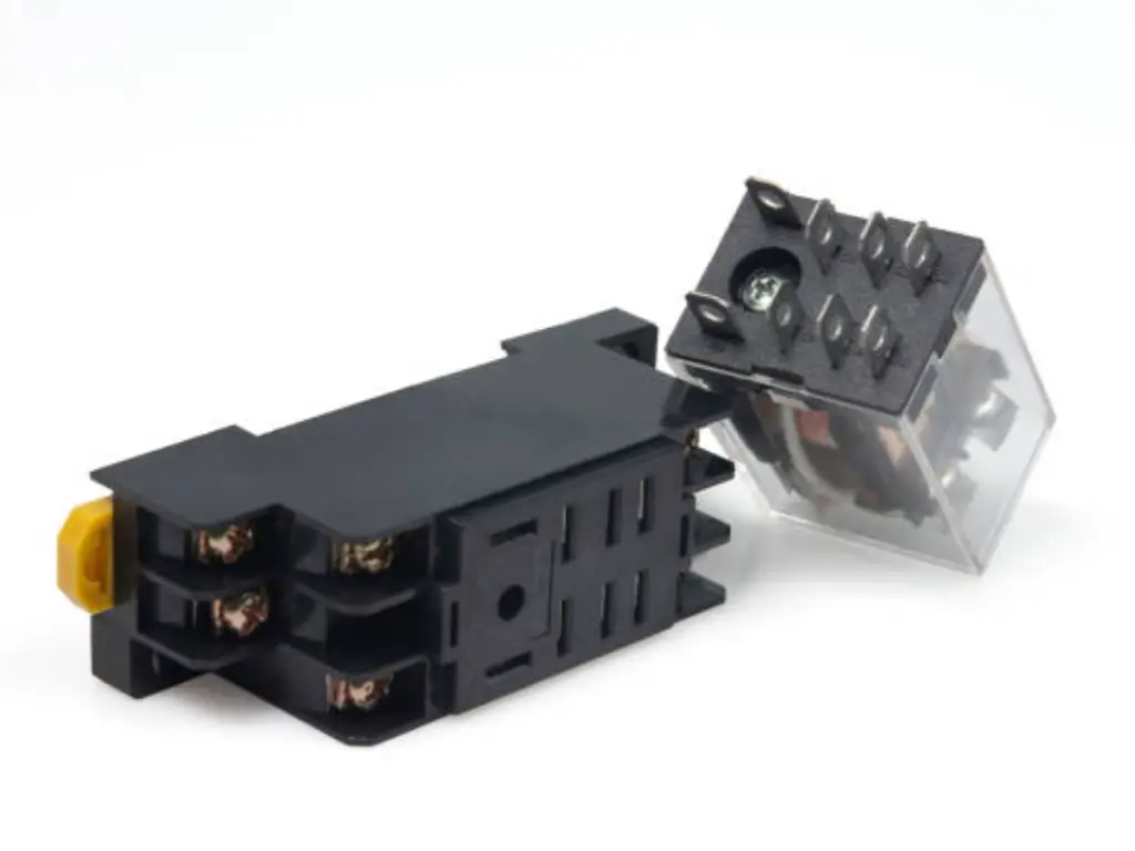
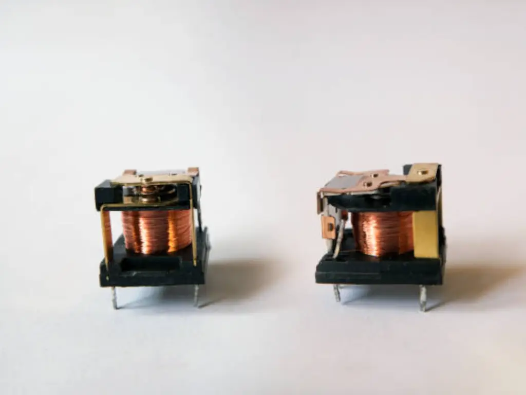
How Mechanical Relays (EMR) Work
An Electromechanical Relay (EMR) is based on magnetism and physical motion principles which were trusted since more than a hundred years. It is simple to do this:
- A coil of wire is powered by a low power consumption control voltage making an electromagnet.
- A movable armature is attracted to this magnetic field.
- Physically moving the armature completes a series of mechanical links forcing a pair of contacts together, completing the main circuit and enabling the high power load to turn on. Removal of the control signal causes the magnetic field to collapse, one of the springs to pull the armature inwards, and the contacts to open, making the circuit to break.
It is a simple, direct and strong way to switch on/ off, but it depends on the use of mechanical components and these may wear off with time.
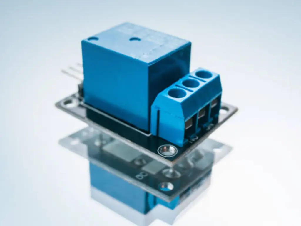
How Solid-State Relays (SSR) Work
On the contrary Solid-State Relay has no mechanical components. It makes use of the characteristics of semiconductor devices to accomplish the same effect:
- A weak control signal is imposed on and input circuit, which is usually an LED.
- Light signal of this LED passes through an open space and is sensed in a photosensitive optocoupler (semiconductor). There is great electrical isolation between the input and output due to this opto-isolation.
- The photodiode switches an electronic switching device on the current-carrying side, usually within the high power part of the load circuit, often a TRIAC or MOSFET but on occasions another switching device.
Since it is all electronic in nature, it works very quietly, extremely fast and devoid of the wear-and-tear that bedevil its counterpart.
Feature
| Component | Mechanical Relay (EMR) | Solid-State Relay (SSR) |
|---|---|---|
| Action | A physical lever moves to connect/disconnect a circuit. You hear a “click.” | An electronic switching device modulates power flow. It operates silently. |
| Control | Binary: completely ON or completely OFF. | Can be switched ON/OFF instantly and can manage power precisely. |
| Wear & Tear | The physical mechanism can wear out after many uses. | No moving parts to wear out, offering a much longer operational life. |
Key Performance Metrics: A Head-to-Head Comparison
Understanding the deep-seated differences in performance is crucial for any engineer. The choice is rarely about which relay is “better” overall, but which is superior for a specific task.
Switching Speed
The speed of an EMR is constrained by the physics of the mechanical elements of the device- the period in which the magnetic field will create and the time necessary to move the armature. This is normally within the range of 5ms to 15ms.
A SSR with no physical limitations is orders of magnitude quicker. It has switching time expressed in microseconds (us) or even nanoseconds (ns). An SSR is the only alternative where the application is such that it needs high frequency Pulse Width Modulation (PWM) or frequent cycle machine control.
Lifespan
It is one of the main differences. Mechanical wear predetermines the life of an EMR. Every time it is cycled, its contacts undergo metal fatigue and electrical arcing and therefore has a lifespan of only the tens or hundreds of thousands of cycles or a few million cycles.
On the contrary, an SSR does not have any moving components that wear out. Its lifetime is bound by its semiconductor lifetime which can be on the order of tens or even hundreds of millions of cycles and therefore it is the obvious product of choice when high tens of millions of cycles or greater lifetime is needed.
Audible Noise
The difference in this case is categorical. There is a characteristic click upon each actuation, produced by EMR internal contacts making or breaking. This does not matter in most industries.
But this noise is not tolerable in medical equipment, top-quality audio systems or in quiet offices. The SSRs have no sound, and this property is vital as the application where confidentiality and absence of noise are paramount.
Shock and Vibration Resistance
The physical nature of an EMR, the coil, spring, and armature it consists of, predisposes it to the event of external shock and vibration. A large shock may result in the contacts bouncing or even the accidental change of state.
Because an SSR is effectively a block of potted electronics, shock and vibration resistance is extremely high leading to a proven and tested performance in harsh applications such as automotive, industrial equipment and aerospace.
Power Consumption
An EMR consists of a coil; to maintain the EMR in an “on” state, the coil needs to be energized as much as necessary N continuous amperes x power P Suppose an EMR consumes 10 amperes at 240 volts; then, to keep the EMR on power P = (10 amps) (240 v) = 2400 watts At that, 10 amperes is the amount of electric current passing through the coil.
Although this load is low, when multiplying it by hundreds of relays in large systems, it may turn out to be quite high energy consumption. A very small amount of power is required to turn on an SSR and turn on its internal LED, and subsequently the power use of an SSRs control circuit is essentially nil, and therefore the SSR is far more energy-efficient.
Heat Dissipation
The advantage here changes. The metallic contacts of an EMR provide very low on-state resistance, i.e. when the relay is activated, very little power of heating takes place.
Slightly less on-state resistance is provided by an SSR as a semiconductor device. This makes it produce a lot of heat which depends on the load current through it. When used with large loads of more than a few amps, an SSR requires the attachment to a heat sink to remove this thermal energy and avoid overheating which can increase the size and complexity of a solution.
On-State Resistance
As explained earlier, the resistance of an EMR is almost zero (being measured as milliohms) yet it is termed as closed circuit. This makes the power flow out to the load as much as possible and causes the least amount of voltage drop.
The resistance when in the on state is a measurable value giving rise to an operating voltage drop across the relay (i.e. ~1V). This drop is negligible to most applications but in low voltage systems where high current flows this loss may have to be taken into consideration.
Leakage Current
An EMR contacts offering a dead end when the EMR is off will leave a contact gap that forms nearly a perfect open circuit, having virtually zero current-leakage.
An SSR may have its output semiconductor circuitry designed to leak only a tiny amount of current when the SSR is off. With most loads this is irrelevant. Yet with very sensitive input devices or, in some cases, medical equipment, such leakage may be a problem, in which case an EMR is preferable.
Electromagnetic Interference (EMI)
Both types of relays may produce EMI, although in dissimilar fashion. Due to the changing between open and closed states, the contacts of an EMR could generate very broadband electrical noise at the level of the arcing.
An SSR does not conduct any form of arc but the rapid switching over of the semiconductors within the SSR are able to produce high-frequency EMI. But SSRs that use a so-called zero-crossing technology turn on or off only when the AC voltage is close to zero, which radically minimizes EMI being generated.
Cost
An EMR is nearly always lower per-unit cost on initial procurement than a similar SSR. EMR is appealing to simple and low-cycle applications in which the initial BOM (Bill of Materials) cost is the key motivator. Nonetheless, the actual cost should be considered throughout the life time of the product. A far longer life, and greater reliability of the SSR, means that no costs are incurred on replacements and maintenance, and that the Total Cost of Ownership (TCO) can be lower, especially with demanding applications.
Key Metrics: Head-to-Head Comparison
| Metric | Electromechanical Relay (EMR) | Solid State Relay (SSR) | Winner for Demanding Applications |
|---|---|---|---|
| Switching Speed | Slow (5-15 ms) | Extremely Fast (µs-ns) | SSR |
| Lifespan | Limited (Mechanical Wear) | Extremely Long (No Moving Parts) | SSR |
| Audible Noise | Audible “click” | Silent Operation | SSR |
| Vibration/Shock | Susceptible | Highly Resistant | SSR |
| Power Consumption | Higher (Continuous Coil Power) | Very Low (Input Circuit Only) | SSR |
| Heat Dissipation | Negligible | Significant (Requires Heat Sink) | EMR |
| On-State Resistance | Very Low | Low, but higher than EMR | EMR |
| Leakage Current | None (Air Gap) | Small Leakage Current | EMR |
| EMI | Arc-induced EMI | Switching EMI (Can be managed) | SSR (with zero-crossing) |
| Initial Cost | Low | Higher | EMR |
| Total Cost of Ownership | Higher in high-cycle use | Lower in high-cycle use | SSR |
Choosing Your Relay: Application-Specific Scenarios
Theory is useful, but decisions are made in practice. Here is how to apply this knowledge to real-world design challenges.
For Industrial Automation & Robotics
A part might have to change thousands of times in a day in a PLC controlled system or a robot arm. The most appropriate is an SSR. Its high longevity is not negotiable to allow expensive shutdown in maintenance. Its fast capacity to switch is high enough to keep the processes accurate and its ability to resist the constant shaking of machines makes it perfect during the working process. Electromagnet does not provide an appropriate solution when compared to electronic switching device that would be used in such environments.
For Medical & Audio Equipment
Consider a patient diagnostic system in a soundproof hospital room or a premium grade audio amplifier. The audible click of an EMR would always be bothersome and distractive. An SSR is needed that does not interfere. It is also a very important safety consideration given the fact that failure isout of the question in medical equipment.
For Demanding HVAC Systems
A major industrial HVAC system requires switching HV power motors and compressors all the time. An EMR would deal with the current but the mechanical contacts would fail soon with such a severe work cycle. The alternate better solution is a well heat sunk SSR. It offers durability so that it could serve the years without replacement. This is particularly significant when one is to determine the kind of load d under consideration which is either inductive or resistive to choose the appropriate output circuit.
For Simple, Cost-Sensitive Projects
Think of a small control panel project as hobbyist or a device that might have a switch that is used only a few times a day. In this case, the longer life and the fast speed of an SSR are unnecessarily large-scale. EMR is a convenient and cost-effective solution. It has low cost to start with and being usable with an easy drive circuit it is equally apt and useful in the task and the cost difference between EMR and SSR comes into more prospect in low frequency usages.
Critical Design Pitfalls and How to Avoid Them
Choosing the right type of relay is only the first step. Proper implementation is critical to unlocking its full potential and avoiding premature failure.
SSR Pitfalls
- Thermal Mismanagement: The most common cause of SSR failure is overheating.
Solution: Always calculate the heating effect (P = V_drop × I_load) and select an appropriate heat sink based on the manufacturer’s data sheet for any load over a few amps. - Leakage Current Surprises: In a circuit with a high-impedance input, the SSR’s leakage current can sometimes be enough to be misinterpreted as an “on” signal.
Solution: A bleeder resistor can be placed in parallel with the load to shunt the leakage current. - Mismatched Load Type: Using a standard zero-crossing SSR for highly inductive loads can be problematic.
Solution: Use a “Random Turn-On” SSR for inductive loads to allow for precise switching.
EMR Pitfalls
- Contact Arcing and Wear: Switching inductive loads leads to arcing, which degrades contacts.
Solution: Add an RC snubber network across the contacts to absorb arc energy. - Coil EMF Kickback: When current to the coil is cut, a voltage spike may damage the control system.
Solution: Place a flyback diode in parallel with the coil.
Ensuring Reliability: Sourcing High-Quality Components
You have considered putting the principles into use, contrasted the measures and realized the design dangers. You have probably arrived at the logical conclusion that a Solid-State Relay is the way to go, because-you require high speed, long life and silent, reliable operation of your application.
Here it involves the second decisive decision. SSRs as we have observed are advanced electronic devices. Their reliability does not only depend on the product design of the device, but also the quality of semiconductors in them, their thermal integrity, and their manufacturing process. All the theoretical properties of an SSR are rendered useless when the device fails early on in its lifespan because of overheating or an inability to receive its rated load.
That is why the selection of a specialized supplier is of primary importance. At OMCH we engineer and manufacture industrial grade Solid-State Relays that you can, and will, build your reputation on. We realise that our components are not only commodities on a BOM, but they are the common denominators in ensuring that your system is up and performing. We are committed to quality production, and exacting test procedures which gives you an SSR that performs to spec, cycle after cycle, year after year. Once you have decided that an SSR is your solution, then working with an expert in the field such as OMCH can help make the reliability you made on paper a reality in the field.
The Future: Hybrid Relays and Next-Gen Tech
The world of relays still develops. Trying to unite the advantages of both worlds, Hybrid Relays are coming. Frequently the high-stress loads of turning off and on (eliminating arcing) are controlled via an SSR, and the bulk current via a parallel EMR with its ultra-low resistance, minimising heating. Additionally, SSRs are likely to be transformed by the development of wide-gap semiconductors such as Gallium Nitride (GaN) and Silicon Carbide (SiC) that would make these devices further miniaturized, with greater efficiency and higher pressure and frequency operating capabilities.


