


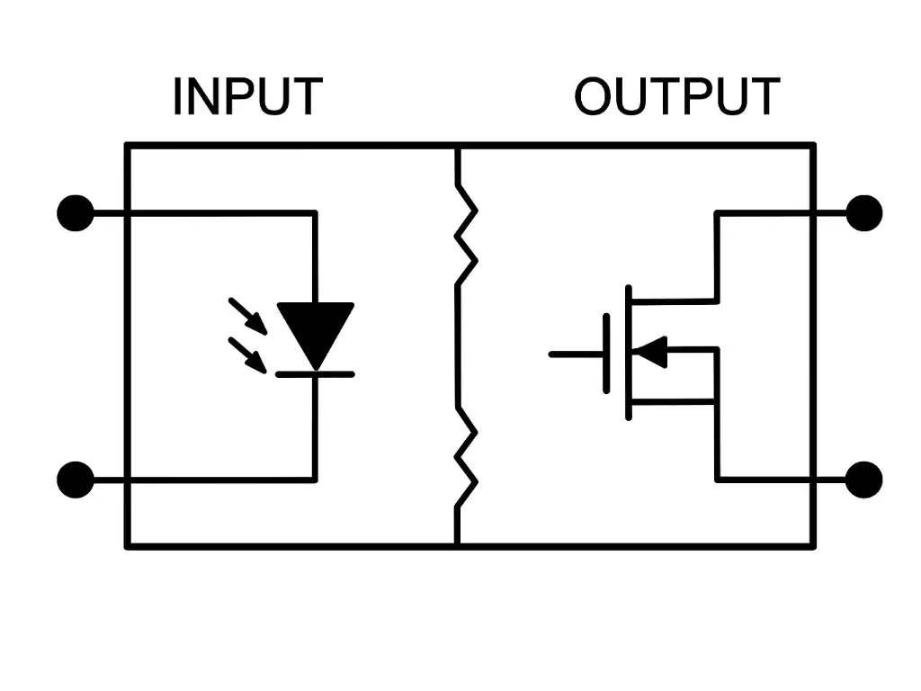
Solid State Relay Symbol and Circuit Representation
Symbols in the language of circuit diagrams are not some scribbles on paper – they are made out of function. The symbol of a solid state relay (SSR), even when shown as a simple shape, conveys an amount of electrical abstraction in one view. Traditionally, an SSR was represented in the form of a rectangular box divided logically into two parts: input and output. This division cannot be recognized as only artistic symmetry but as the main feature of SSRs electrical isolation.
A diode, often labeled with arrows to show an LED (Light Emitting Diode) is used to show the input side. It refers to the opto-isolation device in the SSR: when the input side receives a low (but not zero) voltage DC signal, the LED turns on, giving the output side a signal, but there is no physical electrical connection between the two.
The output side also shows various components as the aights switching capability of the relay is AC or DC. The SSR X output is an AC output SSR that has a TRIAC or two inverse-parallel SCRs (Silicon Controlled Rectifiers), both a type of thyristor, a semiconductor device. In DC variants, a power transistor (a MOSFET or an IGBT) is illustrated. The symbols connote the switching action of the solid state relay circuit and its ability to control output current and output voltage.
To depict a longer schematic the isolation barrier can be symbolized by a zigzag, or an opto-coupler symbol: a diode opposite a phototransistor in a circle. This division between the control circuit and load side is not ornamental it emphasises the dielectric isolation, frequently graded in kilovolts.
Solid State Relay Wiring Diagram and Terminal Identification
The SSR symbols are useful in getting the meaning of functions in a circuit, but wiring diagram brings the functions into reality. It is important to learn how to wire a solid state relay so as to safely and effectively employ it in practical circuits.
Terminal Identification
Most solid state relays follow a standard pin configuration:
- Terminals 3 and 4 (Input side): Input of DC control signal. They are polarity-sensitive in DC-controlled SSRs, the terminal 3 is normally at high potential. This is the input circuit part and makes the output conduction.
- Terminals 1 and 2 (Output side): When SSR is switched, the current flow between these two is switched as well that is why it regulates the current flow in a load.
Wiring Examples
- AC Load Switching (AC-AC SSR)
[PLC DC Output] ───(3 SSR 4)─── [Input Side]
                           │
                       [Isolation Layer]
                           │
[AC Power Supply] ───(1 SSR 2)─── [AC Load]- Input: DC signal (e.g. 5V/ 24V DC signal of a PLC)
- Output: AC voltage switching a heater, lamp, or motor
Such is a characteristic of a single phase ac solid state relay.
- DC Load Switching (DC-DC SSR)
[Microcontroller] ───(3 SSR 4)─── [Input Side]
                           │
                       [Opto-Isolator]
                           │
[DC Power Supply] ───(1 SSR 2)─── [DC Load]- Input: TTL or 5V logic
- Output: Switches 12V, 24V or higher DC circuits
This wiring is standard for single phase dc relay applications.
Wiring Considerations
- Polarity Matters: DC SSRs in particular may be destroyed by connecting tips of input or output at reversed polarity.
- Load Type: where the loads are inductive in nature, the loads must be connected with snubbering circuits or varistors, which absorb the high potentials.
- Mounting: Heatsink integration maybe necessary according to the current and the duty cycle.
Input Side Circuit – LED and Phototransistor Isolation
Optical isolation is the cornerstone of the SSR. Once the input signal is applied across the control terminals, usually a PLC or microcontroller signal, it drives an internal LED. Light energy emitted does not traverse a wire but a transparent dielectric layer, where it energises a photosensitive component, which may be a phototransistor, phototriac or a photodiode array.
This design ensures:
- Electrical isolation of control and load completely
- Immunity to noise: no back emf or transients would be passed to the control logic
- More security, particularly in high-voltage industrial settings
This is a light-triggered action that energizes the gate of the output transistor or thyristor, essentially switching the load without mechanical entanglement or electromechanical relay (EMR) motion.
AC Output Side Device Structures: SCR vs TRIAC
- TRIAC Structure
TRIAC is a bidirectional switch capable of conducting in and out directions upon triggering. In a functional point of view, it combines two SCRs in reverse-parallel to a single package. It is very suitable in medium power AC, like lighting or heating, where a sine wave can be switched at a mid-point to reduce EMI.
The TRIACs are however, prone to false triggering under inductive environments because their commutation immunity is low. In these applications, designers might opt more durable one.
- Inverse-Parallel SCR Structure
This is a bidirectional two-discrete SCR reverse-parallel configuration. One of them, each SCR, conducts half of the AC cycle. Their greater thermal conductivity and improved dv/dt of ability allows their use on loads with high inertia and inductance, such as motors, transformers, and industrial solenoids.
Somewhat larger, with a driving circuitry, inverse-parallel SCRs are the order of the day when it comes to industrial-grade ac solid state relay design because of their ruggedness and controllability.
Triggering Methods: Zero-Crossing vs Random Turn-On SSRs
- Zero-Crossing Trigger SSRs
These SSRs await the AC waveform to reach halfway up a sine wave peak-zero-volt point before switching. This reduces electromagnetic noise (EMI) and current spikes and they are ideal with purely resistive loads such as heaters or incandescent lamps. It is also less straining to the load as well as to the switching device.
- Random Turn-On SSRs
These SSRs are intended to be used in fast response applications and will switch as soon as they receive the input signal, irrespective of the AC phase. It can be more precisely timed and finds frequent use in phase-angle control or motor control or devices needing synchronized triggering.
DC Solid State Relays: MOSFET and IGBT Structures
| Feature | MOSFET SSR | IGBT SSR |
| Voltage Range | Up to ~200V DC | 200V to 1200V+ DC |
| Current Capacity | Moderate | High |
| Switching Speed | Very fast | Moderate |
| Efficiency | High (low RDS(on)) | Good (slightly higher losses) |
| Applications | PWM motor drivers, small DC loads | Welding equipment, solar inverters |
- MOSFET Structure
Low to medium DC voltage / current SSRs with MOSFETs are widely used. They run cool and fast and are also very efficient. A good option where space and response time is paramount.
- IGBT Structure
The Insulated Gate Bipolar Transistors (IGBTs) merge the appropriate speed of switching of the MOSFETs and the high-current capacity of the bipolar junction transistors. They are most appropriate in industrial machines requiring strenuous capabilities of handling, particularly high DC voltage and amperes-level achievements of current.
Thermal Management: Derating Curve and Heat Dissipation Design
All semiconductor devices generate heat, and SSRs are no exception. Excessive temperature leads to reduced current capacity and eventual failure. The derating curve found in most SSR datasheets shows the relationship between ambient temperature and allowable output current.
For instance, a relay rated at 25A at 25°C might only support 15A at 60°C. To counter this:
- Use appropriately sized heat sinks
- Apply thermal grease to ensure full surface contact
- Install SSRs with vertical clearance for airflow
How Does a Solid State Relay Work: Complete Working Principle Overview
Let’s break it down simply:
- Input Signal: A small control voltage (e.g., 5V DC) is applied across the SSR’s input circuit.
- LED Activation: The current energizes an internal LED, which emits infrared light.
- Opto-Isolation: This light crosses an isolation gap and activates a phototransistor or similar device.
- Triggering: The photosensitive device outputs a signal that triggers the gate of the switching device—either a TRIAC, SCR, MOSFET, or IGBT.
- Load Switching: The switching device conducts, allowing load current to flow through the output terminals to the load.
- Switch-Off: When the control voltage is removed, the LED turns off, the photosensor deactivates, and the output circuit opens.
This entire process occurs in milliseconds, silently and without physical contact, unlike traditional EMRs. The beauty lies in its speed, safety, and simplicity.
Application: Specific Advantages and Mounting Styles
There are a number of critical benefits to using solid state relays (SSRs) compared to mechanical relays. They have no moving parts so are noise-free and do not suffer contact wear or erosion by arc action, giving a much longer service life. They are suitable to high-frequency on/offs with very fast switching capabilities, built-in electrical isolation adds system safety as well as prevents ground loop problems. Also, they are not easily shock sensitive or vibration sensitive, hence find applications in unfavorable industrial or automobile settings.
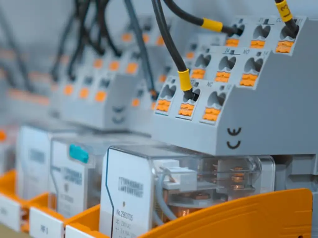
Mounting Styles
Different SSRs can be mounted in different styles to suit the design requirements. The DIN rail mounting is mostly utilized in control cabinets to be mounted easily. Panel mounting facilitates more power and has a stable attachment. PCB mounting Computers of the DIP or SIP types (i.e., user DIP or SIP) is wonderfully suited to both small embedded systems and larger systems.
Real-World Applications
The SSRs are used in medical equipment (such as MRI machines and lab automation) in real-world applications where low EMI and quiet operation are critical. They regulate conveyor systems, heaters, and motors in industrial applications. They are employed in battery chargers, lighting systems and smart plugs in the field of consumer electronics.
SSRs are used more and more to replace mechanical relays of all types and in all types of industry due to their cost-effective safety, smarter, and more reliable use, by giving safer, smarter and more reliable electrical systems because of their silent, electrically isolated, high-speed operation.


