












Почему так важно тестирование электрических компонентов
Любой электрический компонент, лежащий на полке склада, выглядит исправным — пока не перестанет им быть. Реле, которое проходит быструю проверку мультиметром, но выходит из строя после 10 000 циклов переключения. Автоматический выключатель, который срабатывает ровно один раз при номинальном токе, а затем больше никогда. Датчик, который показывает точные показания при 25 °C, но дает погрешность 15% при 45 °C.
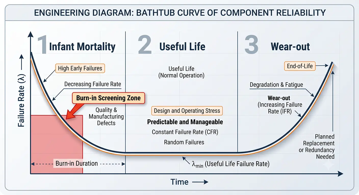
Это не единичные случаи. Они следуют хорошо задокументированной закономерности, называемой «кривой ванны»: всплеск отказов в начале срока службы, длительный период стабильности со случайными отказами, а затем рост числа отказов из-за износа в конце срока службы. Разница между выявлением отказа при входном контроле и обнаружением его в эксплуатации — это разница между возвратом партии товара и отзывом продукции. Для критически важных применений испытания на выжигание — эксплуатация компонентов при повышенной температуре и нагрузке в течение 48–168 часов перед отправкой — позволяют отсеять подавляющее большинство ранних отказов ещё до того, как они попадут на вашу производственную линию.
Представьте себе тестирование так, как вы оценивали бы подержанный автомобиль. Вы бы не купили его только потому, что продавец сказал: “Он отлично ездит”. Вы бы проверили историю технического обслуживания, прокатились бы на нём и, возможно, взяли бы с собой механика. Отчёт о тестировании поставщика — это ваш механик, если, конечно, вы умеете его читать.
Различные должности требуют разного уровня знаний в области испытаний. Технику по техническому обслуживанию необходимо знать, какие испытания подтверждают исправность заменяемой детали. Инженеру по качеству нужно разрабатывать протоколы входного контроля. А специалисту по закупкам — тому, кто подписывает заказ на поставку, — нужно обладать достаточными знаниями, чтобы определить, являются ли заявления поставщика об испытаниях реальными или это всего лишь слова в брошюре.
Четыре основные принципа тестирования компонентов
Тестирование электрических компонентов — это не просто однократная проверка на соответствие или несоответствие требованиям. Это многоуровневая система проверки. Каждый уровень отвечает на свой вопрос о компоненте, и пропуск любого уровня приводит к появлению «слепого пятна».
Визуальный и механический осмотр — первая линия защиты
Это самый базовый этап и, как ни парадоксально, именно его чаще всего пропускают. Визуальный осмотр позволяет заметить признаки неисправности ещё до того, как вы включите измерительный прибор.
Как минимум, проверяйте три вещи в каждой поступающей партии. Во-первых, качество маркировки: нанесены ли номера деталей, коды даты и указатели полярности четко и одинаково на всех изделиях? Поблекшие или несогласованные маркировки часто указывают на перемаркировку — распространенный метод подделки, при котором детали низкого качества перемаркируются как детали более высокого качества. Во-вторых, соответствие размерам: проведите выборочную проверку критических размеров (размер корпуса, шаг выводов, ширина выводов) по сравнению с техническим паспортом производителя. Отклонение в 0,3 мм по шагу выводов может показаться незначительным, но его достаточно, чтобы вызвать образование паяных мостиков на печатной плате с высокой плотностью размещения компонентов. В-третьих, для компонентов со скрытыми соединениями — корпусов BGA, герметично закрытых реле, литых выключателей — Рентгеновский контроль выявляет внутренние дефекты, которые невозможно обнаружить при визуальном осмотре: пустоты в паяных шариках, неправильное расположение внутренних контактов или отсутствующие проволочные соединения.
Системы автоматизированного оптического контроля (AOI) обеспечивают массовый скрининг на производственных линиях, однако у них есть один недостаток: типичный уровень ложноположительных результатов составляет от 5 до 15%. Это означает, что для изделий, выявленных системой, по-прежнему требуется проверка специалистом. Основополагающим стандартом для визуальных критериев приемки является IPC-A-610, который определяет три класса приемлемости в зависимости от критичности конечного применения.
Одного визуального осмотра недостаточно, чтобы определить, исправен ли тот или иной компонент. Однако компонент, не прошедший визуальный осмотр, почти наверняка был произведён на линии, где существуют системные проблемы с качеством — и эту информацию стоит узнать, прежде чем тратить время на более тщательное тестирование.
Испытания электрических характеристик — соответствуют ли они заявленным параметрам?
Именно об этом уровне думают большинство инженеров, когда слышат фразу “тестирование компонентов”. Он позволяет последовательно ответить на три вопроса: есть ли целостность цепи там, где она должна быть? Правильно ли ведет себя компонент при подаче питания? Соответствуют ли измеренные параметры данным технического паспорта?
Статические испытания Ответьте на первый вопрос. Мультиметр или LCR-измеритель позволяет проверять значения сопротивления, ёмкости и индуктивности при отключенном питании компонента. В случае реле это означает проверку соответствия сопротивления катушки значению, указанному в техническом паспорте, а также подтверждение того, что в обесточенном состоянии контакты находятся в состоянии размыкания. В случае конденсатора необходимо проверить как номинальную ёмкость, так и коэффициент диссипации — высокое значение D свидетельствует о внутреннем износе, даже если показания ёмкости кажутся нормальными.
Динамические испытания Ответьте на второй вопрос. Подайте питание и проследите за поведением: скорость переключения реле, частотная характеристика датчика, регулировка по нагрузке источника питания. Компонент, прошедший статические испытания, всё равно может выйти из строя в динамическом режиме — например, транзистор, который показывает правильное значение hFE на криволинейном трассировщике, но входит в колебания под нагрузкой, или твердотельное реле, которое включается корректно, но на выключение у него уходит в два раза больше времени, чем указано в технических характеристиках.
Параметрические тесты Ответьте на третий вопрос, сопоставив каждое измеренное значение с данными технического паспорта — систематически, а не выборочно. Распространенной практикой поставщиков является указание в отчетах только тех параметров, которые прошли проверку, при этом умалчивая о предельных значениях. Надлежащее параметрическое тестирование дает полную картину, и любое отклонение от гарантированных пределов, указанных в техническом паспорте — даже на величину 2% — требует расследования.
Измерение сопротивления контактов показывает, почему важна точность параметров. Для реле общего назначения начальное сопротивление контактов должно составлять не более 50 мОм (в соответствии с IEC 61810-1). Показание 48 мОм на совершенно новом реле технически считается допустимым, но оно опасно близко к пределу — следует ожидать, что в течение первых 20% механического срока службы реле это значение превысит 100 мОм. Показание 15 мОм обеспечивает запас прочности.
Испытания на безопасность — будет ли отказ безопасным?
Испытания на безопасность не являются добровольными. Регулирующие органы требуют их проведения, и на то есть веские причины: компонент, который безупречно работает в нормальных условиях, но при неисправности дает искрение, дымит или замыкается, представляет собой источник риска, а не продукт.
Проверка сопротивления изоляции является первым уровнем защиты. Мегаомметр подает постоянное напряжение — как правило, 500 В для низковольтного оборудования, которое повышается до 1 000 В и более для устройств среднего напряжения — и измеряет сопротивление между проводниками, которые должны быть изолированы. Для большинства промышленных компонентов значения ниже 100 МОм требуют внимания; значение ниже 10 МОм считается критическим нарушением. Это испытание позволяет выявить загрязнённые поверхности, проникновение влаги и изношенные изоляционные материалы — проблемы, которые простая проверка целостности цепи никогда бы не выявила.
Испытание на диэлектрическую прочность, часто называемое испытанием «хипот», идет ещё дальше. Вместо измерения сопротивления при умеренном постоянном напряжении в ходе этого испытания подаётся высокое переменное напряжение — как правило, 1 500 В переменного тока между входом и выходом, а также между входом и землёй — и проверяется отсутствие пробоя. Испытание специально проводится в условиях повышенной нагрузки. Оно подтверждает, что изоляция способна выдерживать переходные перенапряжения без катастрофического отказа. Стандарт IEC 61010-1 устанавливает требования к уровням напряжения и продолжительности испытаний для измерительного и регулирующего оборудования.
Классификация по чувствительности к электростатическому разряду учитывает более скрытую угрозу. Повреждения от электростатического разряда незаметны — компонент может подвергнуться воздействию разряда при обращении с ним, пройти первоначальные электрические испытания, а затем выйти из строя через несколько недель в условиях эксплуатации. Классификация по модели человеческого тела (HBM) варьируется от класса 0 (устройства, выходящие из строя при напряжении ниже 250 В) до класса 3B (устройства, выдерживающие напряжение свыше 8 000 В). Для промышленных условий, где с компонентами регулярно работают, настоятельно рекомендуется выбирать устройства класса 2 (2 000–4 000 В) или выше. Если ваш поставщик не может указать классификацию ESD поставляемых им компонентов, это означает, что он либо не проводит соответствующие испытания, либо не понимает, почему это важно — и то, и другое является тревожным сигналом.
Представьте себе тестирование безопасности как систему подушек безопасности в автомобиле. Вы надеетесь, что она вам никогда не понадобится. Но вам абсолютно необходимо знать, что она работает.
Экологические испытания и испытания на надежность — надолго ли это?
То, что какой-либо компонент прошел все электрические испытания и проверки на безопасность в лаборатории с контролируемым микроклиматом при температуре 23 °C, ничего не говорит о том, как он будет работать на заводе в Юго-Восточной Азии во время сезона муссонов или внутри распределительного щита на производственном цехе сталелитейного завода летом.
Циклическое изменение температуры Именно это и моделирует данный метод. Компоненты подвергаются циклическому воздействию экстремальных температур — типичный профиль составляет от -40 °C до +85 °C с выдержкой в каждой крайней точке и быстрыми переходами между ними. Стандартная процедура определена в стандарте IEC 60068-2-14. Цель испытания заключается не в том, чтобы найти температуру, при которой компонент перестаёт работать, а в том, чтобы выявить слабые места в материалах и соединениях, которые расширяются и сжимаются с разной скоростью. После 500 циклов паяное соединение, которое было на грани разрушения на первом цикле, может расколоться на 500-м цикле.
Испытания в условиях влажной жары — стандарт “двойная 85”: 85 °C при относительной влажности 85% — ускоряет проявление механизмов выхода из строя, вызванных воздействием влаги. В таких условиях резко ускоряются процессы коррозии, дендритного роста на дорожках печатной платы и разрушения изоляции. Для компонентов, предназначенных для установки на открытом воздухе или в помещениях без климат-контроля, прохождение этого испытания является обязательным.
Испытания на вибрацию и удары имеет большее значение, чем думает большинство покупателей. Компонент, прошедший стендовые испытания, может выйти из строя во время транспортировки на грузовике из порта на склад или под воздействием постоянной слабой вибрации при установке рядом с двигателем мощностью 50 HP. Испытания в соответствии с профилями стандарта MIL-STD-810 охватывают как транспортные нагрузки, так и эксплуатационную вибрацию.
На другом конце спектра находится метод ускоренных испытаний на срок службы (HALT). В отличие от испытаний на соответствие, которые проверяют, соответствует ли компонент техническим требованиям, метод HALT подвергает компонент нагрузкам до момента выхода из строя — повышая температуру, уровень вибрации и напряжение сверх номинальных пределов специально для того, чтобы выявить самое слабое звено в конструкции. Полученная в результате информация представляет собой инженерные данные, а не просто отметку «прошел/не прошел». Поставщик, проводящий испытания HALT, понимает пределы возможностей своего продукта. Поставщик, который этого не делает, действует наугад.
По отдельным компонентам: как проходит тестирование различных электрических деталей
Различные электрические компоненты выходят из строя совершенно по-разному. Уязвимым местом реле являются его контакты. У автоматического выключателя — механизм срабатывания. У датчика — дрейф. У источника питания — конденсаторы. Тестирование не может быть универсальным — это индивидуальный подход, основанный на характерных для каждого типа компонентов основных режимах отказа.
Реле — сопротивление контактов, напряжение срабатывания и ресурс переключений
По сути, реле представляет собой переключатель с механическим приводом. Каждое испытание, имеющее значение для реле, связано с этой механической особенностью.
Контактное сопротивление — это параметр, который проверяют чаще всего и который чаще всего неправильно интерпретируют. Начальное сопротивление контактов измеряется путем пропускания тока заданной величины через замкнутые контакты и измерения падения напряжения (четырехпроводной метод Кельвина); для электромеханического реле общего назначения оно не должно превышать 50 мОм. Однако гораздо важнее, чем начальное значение, является динамика изменения этого показателя. Сопротивление контактов, которое изначально составляет 15 мОм и постепенно увеличивается до 35 мОм в течение первых 10 000 циклов работы, говорит о качестве материала контактов. Реле, сопротивление контактов которого изначально составляет 48 мОм, может превысить порог отказа в 100 мОм уже через несколько тысяч циклов.
Напряжение сбора и отпуска В ходе испытаний проверяется, что реле включается и отключается при соответствующих уровнях напряжения на катушке. Реле должно срабатывать при напряжении катушки, не превышающем 80% от номинального значения (то есть реле на 24 В постоянного тока должно срабатывать при напряжении 19,2 В или ниже) и отключаться при напряжении, не ниже 10% от номинального значения. Реле, которому требуется 22 В для срабатывания в системе с напряжением 24 В, будет отключаться при каждом незначительном падении напряжения питания.
Механический срок службы и электрический срок службы Это различие заставляет запутаться даже опытных покупателей. Механический ресурс — как правило, 10 миллионов циклов или более — показывает, сколько раз механизм может физически переместиться до износа, при этом на контакты не действует нагрузка. Электрический ресурс — как правило, 100 000 циклов при номинальной нагрузке — показывает, сколько раз реле может переключать номинальный ток, прежде чем износ контактов приведет к потере надежности. Если в техническом паспорте указано “10 миллионов циклов”, проверьте, о каком именно показателе идет речь.
Автоматические выключатели — проверка кривой срабатывания и отключающая способность
Автоматические выключатели защищают не только электрические цепи, но и людей, и имущество. Их проверка заключается не в том, чтобы убедиться в исправности, а в том, чтобы убедиться, что система защиты действительно работает.
Проверка кривой хода является ключевым элементом испытаний автоматических выключателей. Каждый автоматический выключатель имеет характеристическую кривую — B, C или D в соответствии со стандартом IEC 60898-1 — которая определяет диапазон мгновенного срабатывания. Автоматический выключатель с кривой B должен срабатывать при значениях от 3 до 5 раз превышающих номинальный ток (In). С кривой C — от 5 до 10×In. С кривой D — от 10 до 20×In. Испытания заключаются в подаче точных токов и измерении времени срабатывания, а затем в построении графика, сопоставляющего эти данные с опубликованной кривой. Автоматический выключатель, срабатывающий при 5,5×In, хотя на нём указана кривая B, на самом деле ведёт себя как выключатель с кривой C — и при неправильном применении эта задержка может стать решающим фактором, определяющим, останется ли оборудование защищённым или возникнет пожар.
Разрывная прочность Включает два показателя, которые должен понимать каждый покупатель. Предельная отключающая способность (Icu) — это максимальный ток замыкания, который автоматический выключатель может прервать один раз; после этого он может выйти из строя и потребует замены. Рабочая отключающая способность (Ics) — это ток замыкания, который он может прерывать многократно, оставаясь при этом работоспособным. Отношение Ics к Icu является прямым показателем качества. Соотношение 100% означает, что автоматический выключатель способен многократно выдерживать полный номинальный ток замыкания. Соотношение 25% означает, что это устройство одноразового использования при любых нагрузках, приближающихся к номинальным значениям, указанным на заводской табличке. Для промышленных применений, где возможны повторяющиеся неисправности, требуйте, чтобы Ics было не менее 50% Icu.
Проверка изоляции завершает проверку автоматического выключателя: между фазами, между фазой и землей, а также между размыкающимися контактами. Автоматический выключатель, который срабатывает правильно, но допускает утечку тока между фазами из-за износа изоляции, обеспечивает защиту одной цепи, создавая при этом опасность в другой.
Датчики — точность, линейность и дрейф под воздействием внешних факторов
Датчики — это «глаза» и «уши» любой системы автоматизации, и особенность их отказов заключается в том, что они редко выходят из строя сразу. Они постепенно теряют точность.
Проверка точности и линейности применяет известные эталонные входные сигналы и сравнивает выходной сигнал с идеальной передаточной функцией. В случае индуктивного датчика приближения необходимо приблизиться к стандартизированной металлической мишени с контролируемой скоростью и зафиксировать точное расстояние, на котором происходит переключение выходного сигнала, а затем сравнить его с номинальным расстоянием срабатывания (Sn). Стандарт IEC 60947-5-2 устанавливает допуск ±10% Sn. Датчик с номинальным значением 8 мм, срабатывающий на расстоянии 7,2 мм, находится в пределах допуска — но лишь с небольшим запасом. Датчик, срабатывающий на расстоянии 7,9 мм, обеспечивает почти полный номинальный диапазон.
Для аналоговых датчиков, таких как температурные зонды RTD, точность выражается в виде класса. Датчик PT100 класса A должен обеспечивать погрешность ±(0,15 + 0,002 × |t|) °C во всём номинальном диапазоне — при 100 °C это составляет ±0,35 °C. Датчик класса B при той же температуре допускает погрешность ±0,8 °C. Для управления системами отопления, вентиляции и кондиционирования воздуха (HVAC) эта разница может не иметь значения. Однако для валидации фармацевтических процессов она, безусловно, имеет большое значение.
Время отклика — задержка между изменением входного сигнала и стабилизацией выходного сигнала — это параметр, который в технических характеристиках датчиков часто указывается мелким шрифтом. Фотоэлектрический датчик со временем отклика 1 мс способен обнаруживать детали, пролетающие мимо на высокоскоростном конвейере. Датчик со временем отклика 10 мс при той же скорости конвейера пропустит каждую вторую деталь.
Долгосрочный дрейф — это параметр, который невозможно проверить в ходе одной входной проверки, но который необходимо понять, прежде чем заключать договор с поставщиком. В высококачественных промышленных датчиках скорость дрейфа не превышает 0,1% от полной шкалы в год. Если производитель датчика отказывается обсуждать вопрос о дрейфе при соответствующем запросе, он тем самым посылает сигнал — только не тот, который вам нужен.
Источники питания — пульсации, стабильность при нагрузке и КПД
Блоки питания — это основа, от которой зависят все остальные компоненты системы. При выходе из строя блока питания выходят из строя и все последующие компоненты — причём зачастую с проблемами, диагностика которых обходится дорого.
Пульсации и помехи — это первый параметр, который следует проверить. С помощью осциллографа с ограничением полосы пропускания 20 МГц и подходящего пружинного щупа с заземлением (а не длинного заземляющего провода с зажимом «крокодил» — эта «антенна» улавливает импульсные помехи, которые на самом деле не присутствуют на выходе) измерьте переменную составляющую, наложенную на постоянное напряжение на выходе. Для качественного импульсного источника питания на DIN-рейке пульсации не должны превышать 1% от выходного напряжения. Выходное напряжение 24 В с пульсациями амплитудой 240 мВ (от пика до пика) находится на грани допустимого предела. Значение 50 мВ (от пика до пика) — это отличный показатель. Высокие пульсации означают не просто «шумное» питание — они указывают на то, что выходные конденсаторы выбраны с недостаточной ёмкостью или выходят из строя, а именно эти конденсаторы являются наиболее распространённой точкой отказа в любом источнике питания.
Регулирование нагрузки оценивает, насколько стабильно держится выходное напряжение при изменении нагрузки от нуля до полного номинального тока. Блок питания с хорошей стабилизацией поддерживает выходное напряжение в пределах ±1% во всём диапазоне нагрузок. Проверить это можно, переключаясь между режимами без нагрузки и полной нагрузки и регистрируя переходный процесс напряжения на осциллографе — напряжение должно кратковременно проседать и возвращаться в пределы технических характеристик за миллисекунды, а не постепенно падать при постоянной нагрузке.
Эффективность и тепловые характеристики связаны между собой. Блок питания на DIN-рейке, работающий с КПД 88% при входном напряжении 230 В переменного тока, рассеивает в виде тепла 12% от своей номинальной выходной мощности. При выходной мощности 240 Вт это составляет почти 33 Вт тепла внутри герметичного корпуса. Измерьте температуру корпуса через 2 часа работы при полной нагрузке в условиях неподвижного воздуха — повышение температуры выше температуры окружающей среды более чем на 40 К свидетельствует о ненадлежащем тепловом проектировании, что напрямую сокращает срок службы конденсаторов. Уравнение Аррениуса неумолимо: каждое повышение рабочей температуры на 10 °C примерно вдвое сокращает ожидаемый срок службы электролитических конденсаторов.
Краткий обзор основного испытательного оборудования и стандартов
Для удобства ниже приведена таблица, показывающая соответствие основных категорий испытаний оборудованию и применимым стандартам. Используйте её в качестве отправной точки — всегда сверяйте конкретную редакцию любого стандарта с требованиями к сертификации вашего изделия.
| Категория теста | Основное оборудование | Что измеряет этот прибор | Основной стандарт |
|---|---|---|---|
| Электрические характеристики | DMM, измеритель LCR | Сопротивление, ёмкость, индуктивность, напряжение, ток | IEC 60512, IEC 61810-1 |
| Характеристики сигнала и временные параметры | Осциллограф, логический анализатор | Пульсации, шум, синхронизация переключения, декодирование протокола | - |
| Безопасность | Тестер Hipot, тестер изоляции | Диэлектрическая прочность, сопротивление изоляции | IEC 61010-1 |
| Окружающая среда | Камера для испытаний на температуру и влажность, вибрационный стол | Термоциклирование, влажный нагрев, вибрация, удары | Серия стандартов IEC 60068-2 |
| Срок службы и надежность | Электронная нагрузка, стойка для выжигания | Регулирование нагрузки, эффективность, ускоренное старение | - |
Примечание по выбору оборудования: класс точности имеет большее значение, чем набор функций. В промышленных условиях использование цифрового мультиметра (DMM) с классом защиты не ниже CAT III 600 В является обязательным требованием — применение мультиметра класса CAT II на распределительном щите является нарушением техники безопасности, а не просто ухудшением качества измерений. Испытатель высокого напряжения должен иметь выходную мощность не менее 500 ВА, чтобы обеспечить поддержание испытательного напряжения даже при заряде ёмкости испытуемого устройства.
О стандартах: год издания является частью номера стандарта. Стандарт IEC 61010-1:2010 — это не тот же документ, что и IEC 61010-1:2001. Если в протоколе испытаний поставщика указан стандарт без указания года издания, попросите предоставить эту информацию. Если в протоколе указан отозванный вариант стандарта, спросите, почему.
Как читать отчет об испытаниях, как инженер по качеству
Большинство людей читают отчет об испытаниях так же, как оценочную таблицу результатов санитарной инспекции ресторана — они обращают внимание на букву вверху и переходят дальше. Инженер по качеству же читает его так же, как детектив читает показания свидетеля: каждое число, каждое упущение, каждый странно идеальный результат — это зацепка.
Основные параметры, которые необходимо проверять в любом протоколе испытаний
Прежде чем даже приступить к анализу результатов измерений, проверьте достоверность отчета.
Аккредитация испытательной лаборатории. В достоверном протоколе испытаний указывается лаборатория, проводившая испытания, а также номер её аккредитации по стандарту ISO 17025. Однако одного только номера аккредитации недостаточно — необходимо убедиться, что сфера аккредитации лаборатории охватывает конкретный метод испытаний, указанный в протоколе. Лаборатория, аккредитованная для проведения измерений размеров, не обязательно обладает компетенцией для проведения испытаний на диэлектрическую прочность, даже если оба вида испытаний относятся к категории “электрические испытания”.”
Указанный стандарт и год его издания. В каждом достоверном протоколе испытаний точно указывается, какой именно стандарт был применен, включая редакцию или год пересмотра. Если в протоколе указано “IEC 61010-1” без указания года, это является «желтым флажком». Если в нем упоминается версия, снятая с производства пять лет назад, это уже «красный флажок». Стандарты развиваются — испытание, проведенное в соответствии с устаревшей редакцией, может не соответствовать текущим нормативным требованиям вашего целевого рынка.
Размер выборки и отслеживаемость партий. Отчет об испытаниях типа, основанный на трех тщательно отобранных эталонных образцах, дает совершенно иную картину, чем отчет о плановых испытаниях, подготовленный на основе статистической выборки из производственной партии в 500 единиц. В отчете должно быть указано, сколько единиц было испытано и из какой производственной партии или лота. Если прослеживаемость образцов ограничивается формулировкой “образцы предоставлены производителем”, то перед вами сертификат об испытаниях типа — ценный документ, но не заменяющий данные о качестве на уровне партии.
Измеренные значения по сравнению с предельными значениями. Пометка “Прошел” рядом с каждым параметром означает, что компонент соответствует минимальным требованиям. Однако она не указывает, насколько точно. Контактное сопротивление 48 мОм при предельном значении 50 мОм считается «пройденным» — но контактное сопротивление 12 мОм уже относится к другому изделию. Всегда обращайте внимание на фактические измеренные значения. Поставщик, предоставляющий только сводные отчеты о прохождении/непрохождении, либо скрывает сокращение маржи, либо не понимает, почему маржа имеет значение.
Предупреждающие признаки, указывающие на неэффективные методы тестирования
Некоторые отчеты об испытаниях на первый взгляд кажутся полными, но при тщательном анализе оказываются несостоятельными. Вот на что следует обратить внимание:
В отчете отсутствует номер аккредитации лаборатории. Любая лаборатория, аккредитованная по стандарту ISO 17025, размещает свой номер аккредитации на видном месте. Его отсутствие, как правило, означает, что испытания проводились собственными силами производителя без контроля со стороны третьей стороны — это не является автоматическим основанием для дисквалификации, но значительно снижает степень независимости и достоверности отчета.
Ссылка на отозванные или устаревшие стандарты. Стандарты обновляются не просто так — как правило, потому что в старой версии были обнаружены пробелы в области безопасности или недостаточная строгость испытаний. Если в отчете 2026 года упоминается стандарт IEC 61010-1:2001, это означает либо то, что испытания были проведены несколько десятилетий назад, а их результаты повторно использованы, либо то, что лаборатория не соответствует требованиям своей аккредитации. Ни один из этих вариантов не внушает доверия.
Все измеренные значения одинаковы для всех образцов. В реальных условиях производства всегда присутствуют отклонения. Если в отчете указаны пять образцов с показателями контактного сопротивления ровно 23,5 мОм, 23,5 мОм, 23,5 мОм, 23,5 мОм и 23,5 мОм — эти цифры не были измерены по отдельности; их просто скопировали и вставили. В реальных производственных партиях, даже на хорошо контролируемой линии, обычно наблюдается разброс параметров в пределах 2–5%. Идеальная однородность — самый надёжный признак сфальсифицированных данных испытаний.
Отсутствуют важные категории тестов. Протокол испытаний автоматического выключателя без данных о кривой срабатывания. Протокол испытаний источника питания без результатов измерения пульсаций. Протокол испытаний реле без данных о сопротивлении контактов. Это не упущения — это признания. Испытания не были проведены, и, как правило, на то есть причина.
Даты испытаний предшествуют дате производства партии. Это звучит слишком очевидно, чтобы об этом упоминать, но такое бывает — особенно когда поставщики повторно используют старые протоколы типовых испытаний и представляют их в качестве подтверждения качества конкретной партии. Сверьте дату испытаний с датой изготовления партии или лота, указанной в упаковочном листе.
Вопросы, которые следует задать поставщику по поводу испытаний
При оценке поставщика эти вопросы позволяют отделить тех, кто рассматривает тестирование как одну из основных компетенций, от тех, кто воспринимает его лишь как формальность:
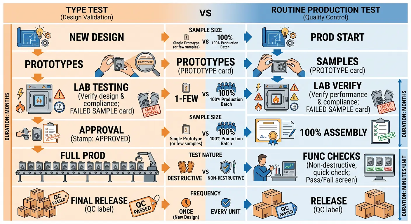
“Это типовые испытания или плановые производственные испытания?” Типовые испытания подтверждают работоспособность конструкции — один раз, на прототипных образцах. Регулярные испытания подтверждают, что каждая отгруженная единица соответствует техническим требованиям. Поставщики, которые не могут четко объяснить эту разницу, — это поставщики, не проводящие регулярных испытаний.
“Когда в последний раз проводилась калибровка вашего испытательного оборудования, и можете ли вы предоставить сертификаты калибровки?” Достоверность испытательных данных зависит от достоверности приборов, с помощью которых они были получены. Калибровка должна проводиться ежегодно и обеспечивать прослеживаемость до национальных или международных эталонов измерений. Поставщик, который проявляет нерешительность в этом вопросе, не проводит калибровку регулярно.
“Можете ли вы предоставить данные испытаний, прослеживаемые по серийному номеру каждого полученного мной устройства?” Прослеживаемость на уровне партии — это «золотой стандарт». Это означает, что в случае сбоя в эксплуатации можно найти конкретную запись об испытаниях именно этой единицы и определить, осталась ли проблема незамеченной или возникла уже после отгрузки.
“Какова ваша политика в случае, если партия продукции не проходит плановые испытания — вы проводите доработку, утилизируете её или отгружаете с уведомлением об отклонении?” Этот вопрос раскрывает о культуре качества поставщика гораздо больше, чем любой сертификат. Правильный ответ включает в себя карантин, анализ первопричин и корректирующие меры — а не “мы будем проводить повторные испытания, пока не получится”.”
“Проводите ли вы какие-либо испытания, выходящие за рамки требований стандартов?” Лучшие производители рассматривают стандарты как минимальные требования, а не как предел. Если поставщик по собственной инициативе сообщает, что проводит дополнительные испытания на выгорание, HALT или тестирование с учетом конкретных условий эксплуатации, выходящие за рамки обязательного набора испытаний на соответствие стандартам, это означает, что он инвестирует в качество, а не просто отмечает галочки в списке.
Проверка покажет, у кого вы на самом деле покупаете
Существует принципиальная разница между производителем, который самостоятельно проводит испытания, и торговой компанией, которая полагается на сертификаты, предоставляемые поставщиками. Чтобы понять эту разницу, не нужно посещать производственные помещения — она очевидна из документации.
Три признака помогут вам отличить производителей, которые серьезно относятся к испытаниям, от тех, кто рассматривает их лишь как формальность:
Испытательное оборудование на объекте. Производитель, располагающий климатическими камерами, высоковольтными испытательными устройствами, стойками для выжигания и калибровочным оборудованием, вложил значительные средства в обеспечение качества, что торговая компания не может повторить с экономической точки зрения. Спросите, какое испытательное оборудование у них есть на собственном предприятии, а какое они заказывают у сторонних поставщиков. Ответ, как правило, многое проясняет.
Регулярные испытания на уровне партии. Если поставщик может предоставить данные испытаний, привязанные к каждой производственной партии — а не только разовый сертификат типовых испытаний, — значит, у него действует настоящая программа обеспечения качества. Если на каждый запрос о предоставлении данных испытаний приходит один и тот же PDF-файл, датированный тремя годами назад, значит, вы имеете дело с организацией, которая занимается лишь бумажной волокитой.
Отслеживание серийных номеров. Возможность найти конкретную запись об испытаниях для конкретного изделия, отправленного конкретному заказчику, — это отличительная черта производителя, который рассматривает качество как часть производственной дисциплины, а не как маркетинговый ход. Внедрение такой системы обходится дорого, поэтому большинство компаний этого не делает — и именно поэтому те, кто это делает, сразу же выделяются на общем фоне.
Для дистрибьюторов и оптовиков репутация зависит от качества продукции, поставляемой вашим поставщиком. Сотрудничество с производителем, который проводит исходящие испытания по стандарту 100% с возможностью отслеживания на уровне партии, означает, что компоненты, которые получают ваши клиенты, в точности соответствуют данным протокола испытаний — для каждой партии и каждый раз. Компания OMCH, располагающая собственными испытательными лабораториями и обладающая более чем 30-летним опытом производства, создана для партнеров по поставкам, которым требуется стабильное качество в больших объемах — узнать о партнерских программах по распространению.
Ваш контрольный список для испытаний электрических компонентов
Используйте этот контрольный список в качестве практического руководства — будь то при разработке программы входного контроля или при оценке нового поставщика. Каждый пункт — это контрольный барьер. Пропустите хотя бы один — и вы полагаетесь на удачу.
Перед оформлением заказа:
- Определите применимые стандарты IEC, UL или GB для каждого типа приобретаемых вами компонентов — убедитесь, что год издания актуален
- Запросите у поставщика протокол типовых испытаний и убедитесь, что он был выдан лабораторией, аккредитованной по стандарту ISO 17025, сфера аккредитации которой охватывает конкретные методы испытаний, указанные в документе
- Уточните, проводит ли поставщик плановые (на уровне партии) производственные испытания или только типовые испытания — в случае плановых испытаний запросите отчет по пробной партии
- Независимо проверить как минимум одно заявление о сертификации (номер дела UL на сайте iq.ul.com, сертификат ISO в базе данных регистратора)
При входном контроле:
- Визуальный контроль: соответствие маркировки, наличие механических повреждений, выборочная проверка размеров по техническому паспорту (один образец на AQL 1,0, уровень II для критических параметров; AQL 2,5 для внешнего вида)
- Выборочная проверка основных электрических параметров: сопротивление, ёмкость, диодная характеристика/проводимость с помощью откалиброванного цифрового мультиметра (не менее 5 штук из каждой партии, для критически важных компонентов — больше)
- Сравните полученные образцы с эталонным образцом, сохраненным из утвержденной первой партии
- Регистрируйте все результаты проверок с указанием даты, номера партии и идентификационных данных инспектора — незарегистрированная проверка является недокументированной
Для критически важных задач:
- Отправьте образцы в независимую лабораторию, аккредитованную по стандарту ISO 17025, для проведения проверочных испытаний — как минимум, проведите выборочную проверку параметров, наиболее важных для вашей области применения
- Для источников питания и реле: провести внутренние испытания на выгорание (не менее 48 часов при номинальной нагрузке и повышенной температуре окружающей среды)
- Обеспечить полную прослеживаемость партии: каждый серийный номер единицы продукции должен быть привязан к протоколу производственных испытаний
- Если речь идет о безопасности: никогда не полагайтесь исключительно на результаты испытаний, проведенных поставщиком — независимая проверка является обязательной
Ссылки
- Международная электротехническая комиссия. “IEC 61010-1: Требования безопасности к электрооборудованию для измерений, регулирования и лабораторного использования”.” https://webstore.iec.ch/publication/61010-1
- Международная электротехническая комиссия. “Серия стандартов МЭК 60512: Разъёмы для электрического и электронного оборудования — Испытания и измерения”.” https://webstore.iec.ch/publication/60512
- Международная электротехническая комиссия. “IEC 60898-1: Электротехнические приборы — Автоматические выключатели для защиты от перегрузки по току в бытовых и аналогичных установках”.” https://webstore.iec.ch/publication/60898-1
- Международная электротехническая комиссия. “Серия стандартов IEC 60068-2: Испытания на воздействие окружающей среды”.” https://webstore.iec.ch/publication/60068-2
- Международная электротехническая комиссия. “IEC 61810-1: Электромеханические элементарные реле”.” https://webstore.iec.ch/publication/61810-1
- Международная электротехническая комиссия. “IEC 60947-5-2: Низковольтное коммутационное и контрольно-измерительное оборудование — Бесконтактные датчики”.” https://webstore.iec.ch/publication/60947-5-2
- IPC. “IPC-A-610: Приемлемость электронных сборок”.” https://www.ipc.org/ipc-a-610
- OMCH. “Контакты”.” https://www.omch.com/contact/
- OMCH. “Официальный сайт”.” https://www.omch.com/



 English
  Arabic
  Turkish
  Russian
  Spanish
  French
  Indonesian
  Portuguese
  Thai
Thai  Vietnamese