


In the landscape of modern industrial automation, the rotary encoder serves as the “eyes” of the motion control system. As industries have shifted toward Industry 4.0, the necessity of possessing correct, real-time feedback has never been higher. Whether you are designing a high-speed robotic arm, a precision medical centrifuge, or a heavy-duty conveyor system, choosing the correct type of rotary encoder is a strategic decision that impacts system uptime, accuracy, and total cost of ownership (TCO).
This guide is a comprehensive engineering study of the various types of encoders, sensing technologies, and selection models. It is designed to assist you in navigating the complexities of current feedback systems across a wide range of industrial applications.
Decoding the Fundamentals of Modern Rotary Encoder Types
At its core, a rotary encoder is an electromechanical device that converts the angular position of the shaft or mechanical motion into an electrical signal. This signal—whether analog or digital—is then processed by a controller (such as a PLC or CNC) to determine rotational position, velocity, and direction.
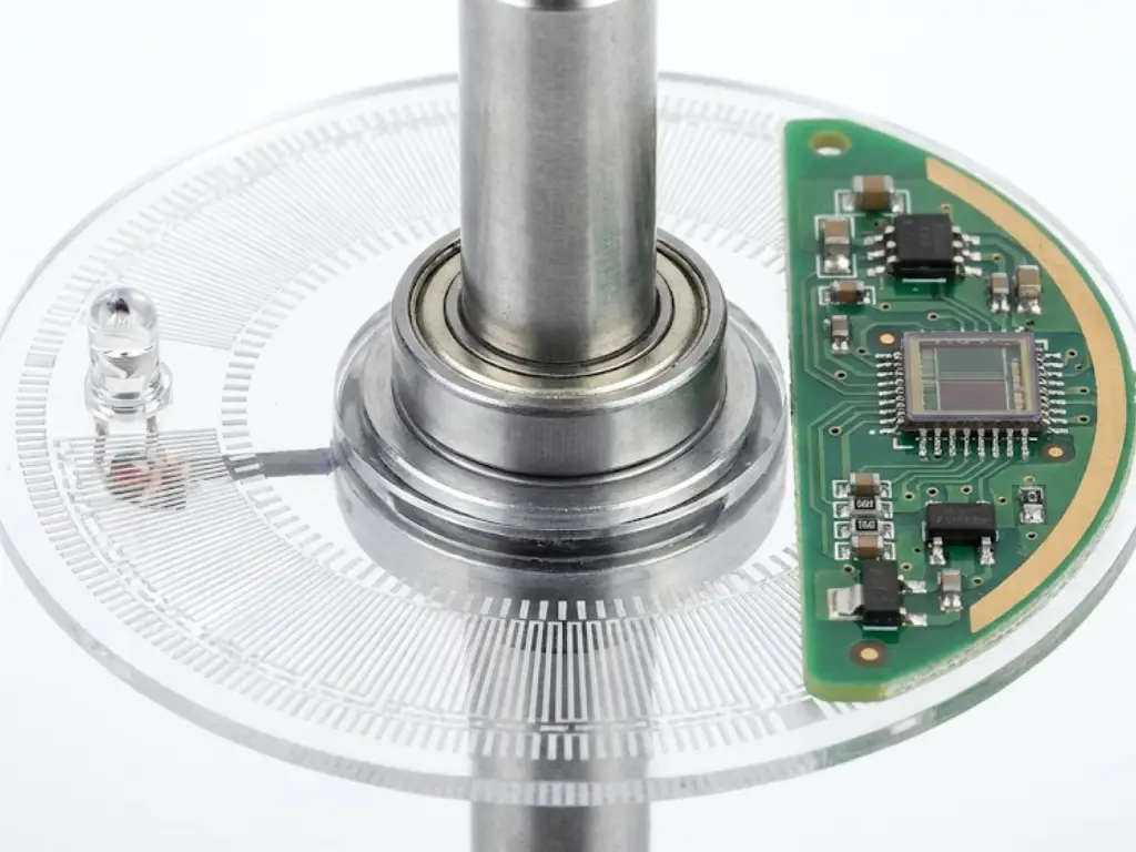
The contemporary encoders consist of four major components:
- The Housing: Protects the internal components from environmental factors like dust, moisture, and electromagnetic interference (EMI).
- The Shaft and Bearing Assembly: The mechanical interface that connects to the rotating equipment.
- The Code Disc or Target: A rotating element (optical disc, rotating wheel, or inductive target) that carries the position information.
- The Sensor and Electronics: The “brain” that detects the changes in the rotating target and converts them into standardized electrical outputs.
The basic worth of an encoder is that it can be used to bridge the digital intelligence and mechanical movement. A closed-loop system uses the encoder to provide the feedback needed by the controller to make instant corrections to the mechanical output to ensure that the mechanical output is identical to the command that is programmed.
Comparing Incremental vs. Absolute Encoders for Precise Control
The greatest crossroad in the selection process is the choice between incremental rotary encoders and absolute rotary encoders. This option defines how the system handles data, especially when power is cycled.
- Incremental Encoders: The Speed and Cost Specialists
Incremental encoders give feedback in the form of a pulse stream as the shaft turns. They normally employ “A” and “B” channels that are 90 degrees apart (quadrature) to identify direction. A third “Z” or index channel provides a single pulse per revolution to establish a reference point.
- How they work: They determine the motion by counting the number of pulses. The type of encoder loses its position in the event of a power outage, necessitating a “homing” sequence to find the zero point again.
- Applications:
- Conveyor Systems: The speed of the belts is monitored and constant velocity is not important, but the absolute position is.
- General Purpose Motor Feedback: This is applied in the provision of RPM information on AC induction motors.
- Simple Human-Machine Interfaces (HMI): Such as volume knobs or menu scrolling wheels.
- Absolute Encoders: The Precision and Security Masters
Absolute encoders provide a unique digital code to every angular position. Even if the power is removed and the shaft is moved, the encoder will report the exact new position immediately upon power-up without needing a “homing” sequence.
- How they work: They use multiple tracks on a code disc to produce a unique binary or Gray code for every increment of rotation. They are also separated into Single-turn (360 coverage) and Multi-turn (counting the number of complete rotations).
- Applications:
- Robotic Joints: In a situation where the exact position of an arm is of concern to safety and precision immediately it begins.
- CNC Machining: This is to make sure that the tool bit is properly positioned to avoid the expensive damage of the workpiece.
- Satellite Antennas: Orientation data storage in sleep modes of power saving.

Optical vs. Magnetic vs. Inductive: Matching Technology to Environment
The ultimate resilience and high accuracy of an encoder are defined by the “how” of sensing. These technologies do not all flourish in the same environment, making technology matching a vital part of the engineering process.
- Optical Sensing: The Gold Standard for Precision
Optical rotary encoders utilize a high-intensity LED light source and an optical sensor (photo-detector array) to scan patterns on a code disc.
- The Physics: It relies on the interruption of light. This allows for incredibly fine increments, translating into ultra-high resolution.
- The Constraint: Since it is a light based technique, a tiny dust particle or a film of oil on the disc can result in “missed counts”.
- Best For: Cleanroom environments, semiconductor fabrication, and high-accuracy laboratory automation.
- Magnetic Sensing: The Robust Workhorse
Magnetic rotary encoders use a permanent magnet and a specialized sensor, often utilizing the hall effect or magnetoresistance, to detect changes in the magnetic field.
- The Physics: Since magnetic fields penetrate through non-magnetic materials, the internal components can be completely encapsulated (potted).
- The Constraint: While virtually immune to liquids and dust, they can be “blinded” by strong external magnetic fields from nearby high-power motors or brakes.
- Best For: Food and beverage (wash-down areas), heavy construction machinery, and outdoor wind turbines.
- Inductive Sensing: The Rugged Alternative
Often overlooked in basic guides, inductive encoders use electromagnetic induction between a moving metal target (the rotor) and a stationary set of coils (the stator).
- The Physics: It works similarly to a transformer. It is naturally resistant to virtually any kind of contamination such as oil, water, and metal shavings, and it is not affected by DC magnetic fields.
- The Constraint: Typically more expensive and features a larger physical footprint than compact magnetic models.
- Best For: Aerospace actuators, subsea exploration, and high-reliability defense systems.
The Environmental Matching Model (Selection Matrix)
We have created this decision model to assist you in making a decision based on the typical industrial stressors:
| Environmental Stressor | Preferred Technology | Why? |
| Heavy Oil/Coolant | Magnetic / Inductive | Optical discs will fail if coated in opaque fluids. |
| High EMI/Magnetic Fields | Optical / Inductive | Magnetic sensors will suffer from signal “jitter” or offset. |
| Extreme Shock/Vibration | Magnetic / Inductive | Glass optical discs are prone to shattering under high G-loads. |
| Ultra-High Precision | Optical | Currently, no other tech matches the sub-arcsecond resolution of optics. |
| Submerged/Vacuum | Inductive | High reliability with no sensitive optical or magnetic components. |
Navigating Mechanical Interfaces: Solid Shaft vs. Hollow Shaft Designs
In industrial motion control, the mechanical interface is the primary point of failure. While electrical errors can often be fixed with software or shielding, a mechanical mismatch leads to catastrophic bearing failure or signal drift. Choosing between solid and hollow shaft designs is a balance of spatial constraints, installation precision, and vibration damping.
- Solid Shaft Encoders: Precision via Isolation
The traditional one is solid shaft encoders (typically 6mm, 8mm or 10mm diameter) that are employed in high-end applications.
- The Coupling Factor: These require a flexible coupling (bellows, helical or oldham) to fit to the drive shaft. This bond is a sort of “mechanical fuse”, that accepts angular, parallel and axial misalignments.
- Mechanical Stress: n solid shaft designs, isolating the encoder bearings of the thermal expansion and the axial “play” of the motor shaft can lead to a longer L10 bearing life.
- Installation Angle: It is time consuming because it incorporates proper positioning of two separate shafts. However, it is substitutable with the minimum of effort- in the event that the encoder is broken, you can change the unit without the need to disassemble the main drive.
- Hollow Shaft Encoders: The Space-Saving Integration
Through-bore hollow shaft encoders are mounted on the shaft of the motor by a collar or clamp.

- Space & Footprint: Because they eliminate the need for a coupling and a mounting bracket, they significantly reduce the axial footprint of the motor assembly. This is imperative in robotic joints and miniature medical equipment.
- Vibration Resilience: In high-vibration environments, hollow shaft encoders are often superior. As the encoder body is connected to the machine frame through a so-called “stator coupling” (flexible spring plate), the whole unit moves with the shaft and reduces high-frequency jitter in the signal.
- Blind Hollow Shaft: This is a special type of shaft in which the shaft is fully penetrated. This has the minor benefit of a hollow shaft with the added security of dust and moisture entering the back of the motor.
- Impact on Installation Complexity and Stress
| Interface Type | Installation Time | Misalignment Tolerance | Mechanical Stress Point |
| Solid Shaft | High (Requires alignment) | High (Absorbed by coupling) | Coupling wear/fatigue |
| Hollow Shaft | Low (Slide-on) | Low (Fixed by shaft fit) | Encoder bearings (Direct load) |
Digital Communication Protocols: From SSI to Industrial Ethernet
In the traditional landscape of motion control, an encoder was a “passive reporter”-it merely sent pulses or a single position value to a controller. However, the rise of Industry 4.0 and the Industrial Internet of Things (IIoT) has fundamentally shifted the feedback logic. Rotary encoders are now intelligent nodes, and can be used to communicate in both directions, and far beyond position tracking.
- The Shift from “Blind” Feedback to “Aware” Data
Classical protocols such as SSI (Synchronous Serial Interface) or BiSS-C are very fast and reliable in point to point communication. But they are “blind” to their health. When an SSI encoder malfunctions because of too much vibration or a dirty code disc, only a signal loss or an error bit is detected by the controller, usually after the machine has already crashed.
This logic has been redefined by modern protocols such as IO-Link and Industrial Ethernet (EtherCAT, PROFINET) which provide a “service layer” in addition to the “process data layer”.
- IO-Link: The “USB” of Industrial Sensors
The lower level of automation has been transformed by IO-Link. It is the initial global standardized IO technology (IEC 61131-9) of communication with sensors and actuators.
- Logic Change: An IO-Link encoder is not only able to send position data but also parameterizes and offers diagnostics.
- Key Advantage: In case an encoder is broken, you can insert a new encoder, and the IO-Link Master will automatically “download” the former configuration to the new device. This minimizes Mean Time to Repair (MTTR) to minutes.
- Predictive Insight: It can report internal temperature or warning flags (e.g., “Lens Contamination”) before a failure occurs, moving maintenance from reactive to proactive.
- EtherCAT: Real-Time Synchronization and Beyond
In high performance applications such as multi-axis robotics or CNC machining, EtherCAT is the standard of the future-oriented engineering.
- Distributed Clocks (DC): EtherCAT encoders use hardware-based synchronization that allows axes to be synchronized with jitter of less than 1 microsecond. This is essential in applications where a number of motors need to move in perfect synchrony.
- Decentralized Logic: Unlike SSI, where the PLC does all the heavy lifting, an EtherCAT encoder can handle some pre-processing of data, reducing the computational load on the central controller.
- Simplified Topology: Through “daisy-chaining,” you can connect hundreds of encoders with standard Ethernet cables, drastically reducing wiring complexity and the potential for EMI-induced signal errors.

- The Forward-Looking Edge: Encoders as Edge Devices
The greatest technical improvement in encoder protocols is the adoption of Edge Computing capabilities.
Future-ready encoders are now being equipped to monitor:
- Vibration Analysis: The wear of bearings in the motor itself.
- Operational Hours: Tracking the actual “workload” of a machine for usage-based maintenance.
- Signal Integrity Monitoring: Analyzing the quality of the light or magnetic field internally to predict end-of-life.
Resolution and Accuracy: Essential Metrics for Performance Optimization
The distinction between resolution and accuracy is often the “make-or-break” factor in high-performance motion control. While these terms are frequently used interchangeably in casual conversation, in precision engineering, they represent two fundamentally different aspects of feedback quality.
Resolution: The Granularity of Your Data
Think of Resolution as the number of “notches” or “steps” an encoder sees in one full 360-degree turn. It defines the smallest move the system can possibly detect.
- Incremental Encoders: We measure their resolution in Pulses Per Revolution (PPR). The more pulses, the finer the control.
- Absolute Encoders: These use bits to define resolution. Each additional bit doubles the number of unique positions the encoder can identify (for example, a 16-bit encoder can “see” over 65,000 distinct points in a single circle).
In Practical Terms: If you select an encoder with 10,000 PPR, you are essentially slicing a full circle into ten thousand tiny segments. This means every time the encoder sends a signal, your machine has moved just thirty-six thousandths of a degree (0.036°). This level of granularity is what allows a robotic arm to thread a needle or a CNC machine to carve intricate patterns.
The “Resolution Trap” and System Stability
Another mistake that is frequently made in engineering is excessive specification of resolution in hopes of making the system more accurate. This leads to the “Resolution Trap”: using a high-resolution encoder on a mechanically loose system.
If your resolution is too high relative to your system’s mechanical tolerances (like backlash in gears), the controller may “hunt” for the exact position, causing micro-vibrations and heat buildup in the motor. The trick to optimization of performance is to achieve the so-called “Engineering Goldilocks Zone” where the resolution is sufficient to allow smooth control of the velocity without pushing the mechanical limits of the hardware.
Engineering Metrics for High-Speed Systems
Two other measures are involved when designing high-speed or high-torque designs:
- Repeatability (Precision): The ability of the encoder to provide the same value when the shaft returns to the exact same physical position. For most industrial automation tasks, repeatability is often more critical than absolute accuracy.
- Quantization Error: The inherent “uncertainty” in any digital system, which is typically $\pm \frac{1}{2}$ of the least significant bit (LSB).
Strategic Advantage: The OMCH Performance Guarantee
Performance optimization cannot be discussed outside of manufacturing consistency in the world of industrial components. This is where OMCH offers a clear competitive advantage to both the engineers and the wholesalers.
- Tailored Specification (3000+ SKUs): OMCH does not make you fit into a “one size fits all” solution. With over 3,000 models and specifications, you can select the exact PPR or bit-depth that matches your mechanical system’s requirements. This avoids the waste of over-specification and at the same time you will never miss out on accuracy.
- Certified Accuracy through Rigorous Testing: Unlike generic manufacturers, the production of OMCH is supported by the ISO9001 quality management. All encoders are inspected in three stages:
- Incoming Inspection: Ensuring the purity of optical discs and magnetic targets.
- Process Inspection: Utilizing 7 dedicated production lines to maintain strict mechanical tolerances and prevent eccentricity.
- Outgoing Quality Control (OQC): Verifying that every unit meets its rated arcminute accuracy before shipping.
- Global Reliability for 72,000+ Customers: OMCH encoders have been tested in the field in more than 100 countries, in high precision medical equipment and in rough textile equipment. This huge data set of real-world applications enables OMCH to optimize their designs to achieve the highest Signal-to-Noise Ratio (SNR) so that the high resolution you are paying to is not wasted on electrical interference.

When you purchase OMCH, you are not purchasing a sensor, you are purchasing a piece of a system that has been developed over 30 years of research and development to offer the “truth” in data that is required in modern industrial systems. Standard pulse count or high-bit absolute signal, OMCH 24/7 technical support will be sure that your “Resolution and Accuracy” metrics are exactly where you want them in terms of machine performance objectives.
Strategic Selection Framework: A 5-Step Decision Matrix for Engineers
The following matrix will help you to simplify your selection process. This model is a balance between technical and commercial feasibility.
The Encoder Selection Matrix
| Selection Criteria | Incremental (Optical/Mag) | Absolute (Single/Multi-turn) | Industrial Ethernet Encoders |
| Startup Behavior | Requires Homing | Instant Position Known | Instant + Diagnostic Data |
| Cost Complexity | Low to Moderate | Moderate to High | High |
| Data Integrity | High (with shielded cables) | Very High (Digital) | Ultra High (Networked) |
| Typical Environment | Clean to Light Industrial | Heavy Industrial | Smart Factories / IOT |
| Maintenance | Periodic Check of Home | Low | Predictive (Self-reporting) |
The 5-Step Process:
- Define Motion Profile: Do you need velocity control (Incremental) or precise positioning (Absolute)?
- Assess the Environment: Will there be oil, dust, or EMI? (Optical vs. Magnetic).
- Mechanical Constraints: Is there space for a coupling, or do you need a hollow-bore design?
- Integration Protocol: What language does your PLC/Drive speak? (SSI, BiSS, or EtherCAT?)
- Evaluate Total Cost of Ownership (TCO): Don’t just look at the price tag. Factor in the cost of “homing” time.
Preventive Maintenance and Troubleshooting for Industrial Encoders
Even the most sophisticated encoders need maintenance in order to achieve their optimum service life.
Common Failure Modes:
- Signal Noise: Often caused by poor shielding or improper grounding. Ensure cables are twisted pairs and shielded.
- Bearing Failure: Usually due to excessive shaft loading or misalignment. Use flexible couplings for solid shafts.
- Contamination: If an optical encoder begins to “skip” pulses, it may be due to oil or dust on the code disc.
Troubleshooting Checklist:
- Check Power Supply: Verify the voltage at the encoder pins (not just the power source) to account for voltage drops in long cables.
- Inspect Connections: Loose wiring in the terminal block is the #1 cause of intermittent signal loss.
- Oscilloscope Verification: Incremental encoders Check the quadrature (90 degrees phase shift) between Channel A and B.
Conclusion
Navigating the different types of rotary encoders requires a combination of mechanical and electronic vision. By understanding the distinctions between incremental and absolute logic, matching sensing technology to your environment, and utilizing a strategic selection model, you can ensure your automation systems operate at peak performance.


