












Pergunte a dez eletricistas “qual é a diferença entre um relé e um contator?” e nove responderão a mesma coisa: Um contator é apenas um relé maior e mais pesado. Abra qualquer tabela comparativa e você verá a mesma história: os relés atuam em correntes inferiores a 10 A ou 15 A, enquanto os contatores assumem a função acima desses valores. Parece bem organizado. No entanto, essa é a maneira errada de pensar sobre ambos os dispositivos, e é por isso que tantas decisões de substituição dão errado na prática.
A diferença entre um relé e um contator não está no número de amperes impresso na lateral. Está no tipo de carga que cada um foi projetado para comutar. Quando você percebe isso, todas as outras diferenças — tamanho, preço, vida útil, qual deles apresenta falha, qual você pode substituir — ficam claras.
Relé e contator: dois membros de uma mesma família de comutadores eletromagnéticos
Comece pelo que eles têm em comum, pois isso representa a maior parte da história. Um relé e um contator são o mesmo mecanismo: uma bobina que transforma energia elétrica em um campo magnético e um conjunto de contatos que o campo faz fechar. Envie um pequeno sinal à bobina — seja um termostato, uma saída de PLC ou um botão — e os contatos ligam ou desligam um circuito muito maior. O lado de controle permanece eletricamente isolado do lado da carga. Essa é a razão pela qual essa família de componentes existe: ela permite que um sinal de 24 V comande com segurança um circuito de 230 V ou 400 V.
Esses nomes são mais antigos do que os departamentos de marketing. Relé vém da ideia de retransmitir, de passar um sinal adiante, que é exatamente o que esses dispositivos fazem nos circuitos de controle. Contator descreve um dispositivo cuja função é entrar em contato em um circuito de potência. Um transmite comandos; o outro fecha um circuito principal. Ambos funcionam com base nos mesmos princípios físicos.
Um relé transmite um comando
Contatos de controle nas formas NA, NC ou de comutação, acionados por um sinal de baixo nível e isolados do lado da carga.
Um contator fecha um circuito de alimentação
Contatos principais que são quase sempre do tipo “NÃO”, com capacidade de supressão de arco e pólos interligados dimensionados para a carga.
Dentro dessa família, há um espectro, e não uma fronteira definida. No lado dos relés, temos relés de placa de circuito impresso (PCB) que comutam sinais de nível lógico, relés plugáveis de uso geral na faixa de vários amperes, relés de potência e relés temporizados que oferecem uma função de atraso. Os relés de estado sólido substituem o contato mecânico por um semicondutor. No lado dos contatores, temos dispositivos que vão de alguns amperes até unidades do tamanho de painéis de distribuição. Um esclarecimento para que o restante deste artigo permaneça claro: quando dizermos “relé” daqui em diante, estamos nos referindo à família de relés eletromagnéticos de controle industrial. Não se trata de relés automotivos, nem de relés de rede, nem dos subtipos temporizados ou de estado sólido, a menos que os mencionemos especificamente.
Mais um termo técnico, já que estamos falando nisso. Os contatos de relé podem ser do tipo normalmente aberto (NO), normalmente fechado (NC) e de comutação; um relé pode ser conectado de forma a interromper um circuito quando sua bobina é energizada. Os contatos principais do contator são quase sempre do tipo NO: quando a bobina está desenergizada, o circuito fica aberto. Se um circuito precisar de à prova de falhas o que importa é abrir.
O espectro de carga: onde cada relé e contator se encaixa
Agora, coloque toda a família em uma única linha: o espectro de carga. O que está sendo comutado e qual é o grau de dificuldade dessa comutação?
O espectro de carga: uma família de chaves, classificada de acordo com o que deve ser comutado
| Classe do dispositivo | Carga típica | O que faz com que seja reversível |
|---|---|---|
| PCB / relé de sinal | Contatos secos, sinais lógicos, circuitos na faixa de mA | Contatos minúsculos, bobina minúscula, cabe em uma placa. |
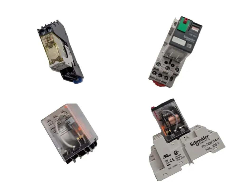
| Relé plugável para uso geral | Circuitos de controle e pequenas cargas, lâmpadas indicadoras, válvulas solenóides, pequenos ventiladores e as próprias bobinas dos contatores | 5 a 10 contatos da classe A, formas NO/NC/comutadoras, substituíveis em soquetes. |
| Relé de potência / contator pequeno | Cargas únicas mais pesadas, motores de bomba, conjuntos de aquecedores, pequenos compressores | Contatos e molas maiores; começa a exigir o controle do arco. |
| Contator multipolar | Motores, compressores, circuitos trifásicos, painéis de iluminação | Paraquedas em arco ou geometria de ejetão; hastes acopladas mecanicamente que se fecham juntas; molas pesadas. |
Observe o que a tabela faz não conter: um único valor de corrente mágica. Isso porque um relé de “15 A” e um contator de “15 A” não são respostas intercambiáveis para a mesma pergunta. Um deles é classificado para suportar 15 A de resistivo constante a corrente e fechar algumas vezes por hora. O outro é projetado para suportar o pico de corrente de partida de um motor, dezenas de vezes por hora, durante anos.
As diferenças estruturais — supressão de arco, material de contato, força da mola e pólos acoplados mecanicamente — surgem exatamente quando a carga se torna difícil de comutar, e são elas que justificam a diferença de preço. Quando você vê um contator que custa várias vezes mais do que um relé com a mesma amperagem, não está pagando por valores nominais maiores; está pagando pela capacidade de interromper um arco sob uma carga indutiva, milhares de vezes, sem que haja soldagem dos contatos.
Os amperes indicados na placa de circuito impresso descrevem o fio. A situação à qual os contatos devem resistir determina o tipo de dispositivo.
toda a diferença, em duas frases
O que realmente faz a diferença: tipo de carga, corrente de irrupção e por que os motores exigem um contator
É aqui que a teoria de que “é só que é maior” não se sustenta, e vale a pena entender isso, pois é também aqui que surgem as falhas de campo.
Por que “Amperagem Suficiente” Não É Suficiente
Uma carga resistiva — como um aquecedor, um conjunto de lâmpadas incandescentes ou um forno de resistência — consome aproximadamente a mesma corrente desde o momento em que é ligada até durante o funcionamento. Um relé dimensionado para essa corrente opera sem problemas durante toda a sua vida útil.
Uma carga indutiva — seja um motor, um compressor ou uma bomba — é um caso à parte. No instante em que os contatos são fechados, o motor ainda não está girando; por isso, ele se comporta como um enrolamento de transformador em curto-circuito e absorve um pico de corrente várias vezes superior ao seu valor de funcionamento. A norma IEC 60947-4-1, que rege as classificações de contatores e acionadores de motor, define os testes AC-3 (serviço de motor) com correntes de aproximadamente seis vezes a corrente nominal. Na prática, picos de partida de compressores de seis a oito vezes a corrente de plena carga são comuns e duram dezenas a centenas de milissegundos até que o rotor atinja a velocidade (IEC 60947-4-1:2023, Aparelhagem de baixa tensão, Parte 4-1).
O número a ser lembrado: um motor pode consumir de 6 a 8 vezes a corrente indicada na placa de identificação durante as primeiras centenas de milissegundos de cada partida.
O número a ser lembrado
6–8×
pico de partida em relação à corrente nominal
nas primeiras centenas de milissegundos de cada inicialização.
Um relé é classificado quanto à corrente de funcionamento. Um contator é classificado quanto a isso.
Os contatos de um relé são selecionados para o constante coluna atual. Ao aplicar uma corrente de partida neles, os pontos de contato formam arcos, espirram e, lentamente ou rapidamente, se soldam. E um contato soldado não simplesmente falha; ele falha fechado. A carga continua funcionando, independentemente do que o lado do controle indique.
Essa é a diferença em uma frase: Um relé é projetado para comutar a corrente de funcionamento da carga; um contator é projetado para comutar a corrente de partida da carga, repetidamente.
A história da Weld: o custo do “Experimente só”
Isso não é teoria, é o motivo de falha mais comum nos fóruns de reparos de sistemas de climatização e refrigeração. Um técnico ou um proprietário decide que o contator é um exagero e instala um relé (ou um substituto barato) no circuito do compressor. Os valores no relé parecem corretos: capacidade nominal de 30 A, e o compressor consome 12. Nos primeiros ciclos, tudo funciona. Então, em uma tarde quente, os contatos ficam soldados durante uma partida. O termostato abre, a placa de controle ordena a parada, mas o compressor e o ventilador do condensador continuam funcionando, pois o circuito de alimentação não passa mais por um interruptor que possa ser acionado por qualquer pessoa. As unidades funcionaram até congelarem completamente ou queimarem antes que alguém desligasse o disjuntor. Em um caso amplamente divulgado, o proprietário descreveu a situação exatamente dessa forma: “a unidade não desligou quando foi ordenado”.”
A segunda cadeia de falhas mais comum começa da mesma forma — contatos subdimensionados —, mas se manifesta inicialmente como vibração. A bobina é ativada com pouca força, os contatos saltam; cada salto gera um arco elétrico, cada arco corrói as faces dos contatos, e essa corrosão agrava o fechamento seguinte. Quando alguém percebe o zumbido, o contator ou relé já está danificado a ponto de não oferecer mais um funcionamento confiável.
A decisão, em três perguntas
Você não precisa de um catálogo para decidir entre relé e contator. Você precisa de três informações sobre a carga:
- Que tipo de carga é essa? Aquecimento por resistência, lâmpadas, válvulas solenóides, circuitos de controle → área dos relés. Um motor, compressor ou bomba → área dos contatores. Alimentação trifásica → contator, sem exceções.
- O que está escrito na placa de identificação? Anote a corrente em carga total e a tensão da bobina/controle. Se for um motor, a corrente de partida é o valor que realmente importa.
- Para qual lado do espectro o aparelho foi classificado? Combine a classe do dispositivo com a classe de carga, e não a intensidade de corrente com a intensidade de corrente.
O relé de estado sólido merece uma menção honrosa aqui, pois é ele que realmente confunde os limites. Um SSR comuta sem contatos mecânicos; portanto, nada se solda, o que o torna excelente para comutações frequentes de baixa corrente, nas quais um relé mecânico se desgastaria. Mas um SSR conduz a corrente por meio de um semicondutor com uma queda de tensão real, e essa queda se transforma em calor que precisa ser dissipado. Para motores e compressores de grande porte, o gerenciamento do calor e dos picos de corrente torna um contator com classificação adequada a melhor opção, e técnicos experientes em refrigeração dirão o mesmo: relés de estado sólido para cargas leves, eletromecânicos para os motores.
Se a placa de identificação não indicar a classe de carga, envie-a para nós e verificaremos a classe e a compatibilidade com o chassi antes de você decidir pela peça.
Envie-nos as especificações da sua placa de identificaçãoRegras e especificações para trocas: o que você pode substituir — e o que deve indicar no orçamento
Então, você tem um equipamento com defeito, não há um substituto exato em estoque e um cliente à espera. Quando você pode substituí-lo por outro modelo? E, ao fazer o pedido, quais parâmetros realmente importam?
As Três Regras da Troca
As três regras de troca e em que casos cada uma delas deixa de se aplicar
| Regra | O que isso significa na prática | Quando deixar de ser aplicável |
|---|---|---|
| A tensão da bobina deve corresponder exatamente | Uma bobina de 24 VCA não é uma bobina de 24 VCC, assim como uma bobina de 110 VCA ou 220 VCA também não o é. Uma tensão incorreta pode resultar em falta de acionamento, acionamento fraco (vibração → contatos queimados) ou uma bobina queimada. Verifique se é CA ou CC e a frequência. | Nunca. Esse é o erro de substituição mais comum na prática. |
| Atual: você pode subir, mas nunca descer | Um contator de 40 A pode substituir um contator de 25 A, desde que a bobina seja compatível e ele se encaixe. Um relé de 25 A não pode substituí-lo, pois o relé nunca foi dimensionado para essa classe de carga (veja o caso da soldagem). | Se a carga tiver mudado (troca do motor, aumento da carga de trabalho), refaça o dimensionamento em vez de partir de suposições. |
| Os postes e os suportes devem ser adequados ao circuito | Um motor trifásico requer um contator de 3 pólos; um substituto unipolar deixa uma fase sem comutação e pode queimar o motor. Verifique se a montagem é em trilho DIN ou no painel e as necessidades de contatos auxiliares. | A adição de contatos auxiliares para sinalização é um recurso, não um substituto. |
É possível usar um contator onde um relé seria suficiente? Tecnicamente, sim, pois a bobina e os contatos funcionam da mesma forma. Mas um contator é maior, mais barulhento, consome mais energia na bobina e custa mais caro. Para a comutação de circuitos de controle, ele não é a ferramenta adequada; é por isso que os engenheiros de painéis reservam os contatores para a potência e deixam que os relés cuidem da lógica. As convenções esquemáticas refletem essa mesma divisão: na maioria dos diagramas de fiação, os relés são numerados como K1, K2… e os contatores como C1, C2…, pois desempenham funções diferentes no mesmo gabinete (Dicas de Engenharia: relés, contatores e acionadores de motor).
O que considerar na cotação: a lista de verificação de seis parâmetros
Quando você faz um pedido, seja para si mesmo ou para um cliente, o fornecedor não consegue ler sua mente, e o número de modelo de uma marca diferente não se identifica automaticamente. Indique estas seis informações:
- Tipo de carga, motor, aquecedor, conjunto de lâmpadas, solenóide. Isso determina a coluna de classificação.
- Corrente nominal E a categoria de utilização, veja a armadilha abaixo.
- Tensão e frequência da bobina, por exemplo, 220 VCA 50/60 Hz ou 24 VCC.
- Número de pólos, 1P, 3P, 4P.
- Contatos auxiliares, quantos contatos NO/NC você precisa para o retorno de status.
- Montagem, trilho DIN, painel ou placa de circuito impresso (para relés).
A armadilha: Muitas fichas técnicas apresentam um único valor de corrente, e se você basear seu pedido nesse número, poderá escolher um contator com capacidade pela metade menor do que a necessária. De acordo com a norma IEC 60947-4-1, o mesmo contator possui duas classificações muito diferentes: AC-1 para cargas resistivas e AC-3 para acionamento de motores. A classificação AC-3 é sempre a mais baixa. Um contator comum de estrutura pequena, por exemplo, indica 32 A em AC-1 e 18 A em AC-3. Exemplos de fichas técnicas de diversos fabricantes mostram o mesmo padrão: um dispositivo que é de “40 A” em AC-1 pode ter apenas 18–25 A em AC-3. Os guias de dimensionamento trazem o mesmo aviso, mas ao contrário: um contator de 25 A AC-1 é não adequado para um motor trifásico que consome apenas 8 A, pois a classificação AC-1 não abrange o pico de corrente na partida. Portanto, quando uma ficha técnica indicar um único valor de corrente sem especificar a categoria, pergunte. A resposta determinará se a peça resistirá à primeira partida.
Conheça os componentes: Partida, Relé de sobrecarga, Disjuntor
Metade da confusão em torno desse assunto vem de três componentes que aparecem ao lado dos relés e contatores em todos os painéis e em todos os catálogos:
Conheça os vizinhos: o que cada dispositivo no armário realmente faz
| Dispositivo | O que ele faz | Quando você precisar | O que NÃO é |
|---|---|---|---|
| Contator | Liga e desliga um circuito de carga mediante comando | Qualquer circuito de motor, compressor ou aquecedor que você precise controlar remotamente | Trata-se de um dispositivo de proteção que não detecta sobrecargas. |
| Relé | Os interruptores controlam sinais e pequenas cargas | Lógica, interposição, status, comutação de baixa potência | Um interruptor de alimentação para cargas indutivas. |
| O motor dá a partida | Contator + relé de sobrecarga em um único conjunto | Circuitos de motores nos quais o motor deve ser protegido contra sobrecargas prolongadas | É só um contator; o importante é o elemento de sobrecarga. |
| Relé de sobrecarga | Monitora a corrente do motor e desarma se o motor consumir corrente excessiva por um período muito longo | Entre o contator e o motor, dimensionado para a corrente nominal de partida (FLA) do motor | Um dispositivo de comutação: ele protege, mas não comuta. |
| Disjuntor | Protege um circuito contra curto-circuito e sobrecarga | A montante do contator, para proteção contra falhas | Um dispositivo de comutação que não se destina ao controle rotineiro de ligar/desligar; sua função é a proteção, e não a comutação cíclica. |
A confusão clássica entre “contator e disjuntor” se resume ao seguinte: o disjuntor protege o circuito contra falhas; o contator o liga quando acionado. Eles são complementares, e a maioria dos circuitos de motores precisa dos dois, geralmente com o relé de sobrecarga entre o contator e o motor.
Quando elas falham: uma lista de verificação em campo para bobinas soldadas, com vibração e queimadas
Os relés e contatores apresentam falhas seguindo alguns padrões reconhecíveis, e esses padrões indicam onde você deve procurar. Quando receber a chamada, siga esta lista:
Soldado na posição fechada / a carga não para → verificar: superfícies de contato (com alimentação isolada) + continuidade entre os contatos principais. Causa principal: dispositivo com capacidade insuficiente para a classe de carga (a corrente de irrupção o soldou), contatos desgastados, força de atração da bobina fraca.
Zumbido / chiado → verificar: a tensão da bobina quando energizada, não apenas em repouso. Causa principal: queda na tensão de controle, transformador com defeito, fiação de controle subdimensionada, tensão da bobina incorreta.
Bobina ou terminais queimados, repetidamente → verificar: tensão nos terminais da bobina ao longo de todo o ciclo, corrente de carga, torque nos terminais. Causa raiz: tensão fora do intervalo permitido, terminações soltas, uma causa no nível do sistema que continua danificando o componente.
Antes de substituir qualquer componente, faça a verificação de 30 segundos conforme as regras de substituição acima: tensão da bobina, classe de carga, corrente nominal e pólos. Uma substituição que repita os erros do dispositivo antigo repetirá sua falha.
E a decisão mais importante nesta página: Se a peça nova apresentar falha novamente em algumas semanas, a causa principal está no sistema, e não no componente. O ciclo clássico é o seguinte: um técnico substitui um contator queimado três vezes em três meses, enquanto o verdadeiro culpado — um transformador de controle com defeito que reduz a tensão da bobina ou um trecho de fiação subdimensionado — permanece intacto a montante. O componente é a vítima; pare de substituir a vítima e comece a medir a alimentação. Nos fóruns de reparos, esse mesmo tópico se repete incessantemente: “a unidade fica queimando contatores”. A resposta que resolve o problema: meça a bobina enquanto estiver em execução e observe a queda de tensão. (Manuseie o lado de controle sob tensão com cuidado; isole o lado de alta tensão antes de tocar em qualquer contato.)
O que isso significa para suas ações e seu balcão
Se você vende esses componentes, todo o artigo até aqui se resume a duas conclusões práticas: sua prateleira precisa das duas classes, e sua equipe de atendimento precisa perguntar sobre a carga antes de perguntar sobre o número do modelo.
A lógica do mercado de ações. Um cliente do mercado de reparos chega com um de dois tipos de problema: um problema de controle (termostato, temporizador, intertravamento, relé) ou um problema de alimentação (compressor, bomba, motor do ventilador, contator). Atenda a ambos e você fechará a venda em uma única visita. No que diz respeito aos contatores, a faixa de operação para a maioria dos serviços de reparo e de pequenos fabricantes de equipamentos originais (OEM) situa-se nos tamanhos comuns de estrutura, aproximadamente de 9 A a 40 A. A família de tensões da bobina é tão importante quanto a corrente: bobinas de 24 VCA e 220 VCA abrangem uma grande parcela dos equipamentos instalados. Dependendo das tensões de alimentação e controle do seu mercado, 380 VCA e 24 VCC formam o próximo nível. No que diz respeito aos relés, mantenha estoque por subfamília, em vez de por modelo: relés plugáveis de uso geral (os de maior rotatividade), relés de potência para a faixa intermediária, relés temporizados para tarefas com atraso e relés de estado sólido para clientes com altos ciclos. Essa divisão não é adivinhação, é o espectro de carga mencionado anteriormente neste artigo, traduzido em espaço nas prateleiras.
O script do contador. Quando um cliente não souber o nome da peça, não pergunte o número do modelo, pois ele não o saberá. Faça três perguntas nesta ordem: Em que canal está passando? (o tipo de aparelho indica a classe de carga) → Com qual tensão de controle ele funciona? (eles podem verificar isso na etiqueta da bobina do contator ou no transformador) → Quantos amperes constam na placa de identificação? Se não tiverem certeza, a orientação mais rápida do ramo: Mande-me uma foto da placa de identificação. Um cliente que descobre que você consegue fazer um diagnóstico a partir de uma foto é um cliente que volta.
Envie a lista de verificação. Imprima a tabela de falhas da seção anterior ou cole-a na resposta do WhatsApp quando um cliente disser “queimou de novo”. A ligação do tipo “troquei e queimou de novo” é onde a maioria dos distribuidores perde dinheiro com devoluções e com a perda de reputação. Um cliente que recebe uma pergunta sobre a causa raiz, em vez de um encolher de ombros, torna-se um comprador recorrente, e a lista de verificação não custa nada a você, a não ser dez segundos para enviá-la.
A escolha de um fornecedor a montante também exige a mesma disciplina. Ao avaliar um fornecedor para essas duas linhas, verifique se ele atende à lista de verificação de cotação da seção de regras de troca, antes de discutir o preço. O atalho prático: o catálogo deles realmente reúne ambas as famílias em um só lugar, com fichas técnicas que respondem aos seis parâmetros? A OMCH é um fornecedor organizado exatamente dessa forma: nossa linha de relés abrange sete famílias — relés de estado sólido, para placas de circuito impresso (PCB), de uso geral, de atraso de tempo, de potência, de proteção e eletromagnéticos —, além de uma linha dedicada de contatores CA dentro de nossa linha de distribuição de baixa tensão. Ambas estão reunidas em um único catálogo com mais de 30 categorias e mais de 3.000 especificações padrão, e disponibilizamos fichas técnicas por modelo por meio do nosso alcance do relé e Linha de contatores CA páginas. Se uma opção da ficha técnica não for adequada para a sua aplicação, nossos engenheiros ajudarão você a escolher a peça certa antes de você fechar o pedido. Essa é uma conversa que vale a pena ter: uma peça que pareça certa no papel, mas que não seja adequada para a classe de carga, é a peça mais cara que você terá em estoque (suporte à seleção de produtos).
Uma observação importante antes de montar essa prateleira: nada disso significa que você deva ter todos os tamanhos em estoque. As estruturas muito grandes e as configurações fora do padrão são de competência de fornecedores especializados e de empresas de projetos, e não de um estoque generalista de alta rotatividade. Mantenha em estoque a faixa intermediária do espectro de cargas, responda primeiro à questão da carga e deixe que a lista de verificação faça o diagnóstico.
Mantenha em estoque o espectro de carga, não apenas um número de modelo — Termos de distribuidores para relés e contatores
Sete famílias de relés e uma linha dedicada de contatores CA em nossa linha de distribuição de baixa tensão, com fichas técnicas, ajuda para referência cruzada e suporte às especificações quando a classe de carga do cliente não estiver clara.
Solicitar preços de distribuidorReferências
- IEC. “IEC 60947-4-1:2023, Aparelhagem de baixa tensão, Parte 4-1: Contatores e acionadores de motor, contatores eletromecânicos e acionadores de motor.” https://webstore.iec.ch/en/publication/74487
- Eng-Tips. “Relés, contatores e acionadores de motor.” https://www.eng-tips.com/threads/relays-contactors-and-motor-starters.73383/



 English
  Arabic
  Turkish
  Russian
  Spanish
  French
  Indonesian
  Portuguese
  Thai
Thai  Vietnamese