


When it comes to industrial automation, the Printed Circuit Board Assembly (PCBA) is the central control unit of the machinery and of important pieces of infrastructure. Industries differ from consumer electronics, however. While controlled environments are the norm in consumer electronics, in industrial equipment and machinery, there is a need to perform in extreme and harsh working environments where there are very high and low temperature ranges, and extreme vibration and electrical noise.
In this industry, the risks related to a single component failing are very serious. The consequences include, but are not limited to, serious and manufacturing costs related to downtimes in production, safety risks, and costs related to lost production. Hence, the primary engineering requirement is to ensure reliability. This guide provides a deep dive into the engineering of industrial PCBA, focusing on the assembly process, essential PCB manufacturing standards, component selection, and painstaking quality control to ensure reliability in operation over a long period of time.
Definition: What is PCBA
In the eyes of an untrained person, a circuit is nothing more than a green board with some silver spots on it. However, to understand the PCBA meaning, one must discern the board from the circuit really.
A PCB, or Printed Circuit Board (historically sometimes called a printed wiring board or wiring board), is the bare board. It is the substrate, the FR-4 fiberglass material with a specific dielectric constant, and copper traces that have been etched to form conductive pathways, and it is potential that just needs to be realized.
PCBA, or Printed Circuit Board Assembly, is the potential that has been realized. It is the assembled board that has electronic components such as capacitors, switches, resistors, and relays that have been soldered onto the board. This transformation from bare PCBs to a functional electronic circuit is the core of the industry.
To say that something as complex as printed circuit board assembly in the industrial control domain is simply the “soldering of some parts to the board” is an extreme understatement. Within the industrial domain, PCB assembly is a field of engineering on its own. It does not constitute simply one step within the manufacturing sphere, but rather an overarching philosophy that includes:
- Supply Chain Management: the guarantee that every single resistor and chip is genuine and remains in circulation for decades.
- DFM (Design for Manufacturing): the arrangement of the components on the board which occurs long before the first board is fabricated so that the board can be manufactured quickly and reliably using various techniques.
- Lifecycle Maintenance: the ability to design a product today and have it be possible to service and repair it in fifteen years.
When undertaking Industrial PCBA, one does not settle for a “job shop” that simply places electrical components on a board. One is establishing the groundwork for the reputation of the product in question.
Industrial vs. Consumer PCBA: Critical Differences
Is it because industrial controllers have a significantly more complex architecture than the processing unit of a consumer tablet? No. It is because of the cost of failure.
While a smartphone is simply rebooted in the case of a glitch, the PLC that manages a blast furnace is a different scenario. Industrial PCBA places a level of importance on reliability that no commercial use electronics require.
IPC Class 2 vs. Class 3 Standards
Quality standards for electronic components assembly are primarily dictated by IPC-A-610 standards.
- Class 2 (Dedicated Service Electronic Products): This class includes most consumer electronics like laptops and home appliances. Such electronic circuits are expected to function and last but their operation is not critical to function.
- Class 3 (High Performance/Harsh Environment Electronic Products): This is the gold standard for medical equipment, industrial automation, and aerospace circuit board assembly.
What makes the difference is the niceties. Consider, for instance, solder fill. For a consumer Class 2 product, a Through-Hole component is fine with achieving only 50% vertical solder fill in the barrel to pass the inspection for it to hold the part in place, and that is sufficient.
On the other hand, a product classified for industrial use in Class 3 requires that same joint to be filled with 75% to 100% solder. This is not only to provide sufficient electrical conductivity, but also for sufficient mechanical stability. It acts as a mechanical structure which bound to absorb shocks by withstanding the continuous vibrations that characterize a factory floor.
Moreover, the visual inspections for Class 3 are extremely detailed. Minor imperfections, like small scratches or certain solder faults, which are merely cosmetic for Class 2, are defects for Class 3. In the realm of Industrial PCBA, we like to say that the only thing standing between order and chaos is perfection.
Resilience in Harsh Operating Environments
Consumer electronics, which consist of collections of devices that are built for convenience, can be housed in pockets or on top of tables in a climate-controlled, safe environment. Industrial electronics, on the other hand, live in the trenches. An Industrial PCBA has to endure:
- Extreme Temperatures: The winter can go as cold as -40 degrees Celsius in an unheated warehouse, and then there’s the furnace to contend with – it can be over 85 degrees Celsius.
- Vibration and Shock: Weak solder joints can fatigue, while standard capacitors can crack. Heavy motors and presses are constantly shaking.
- Contamination: Moisture in the air, conductive dust, oil mist, and corrosive vapor clouds.
But perhaps then there is a greater adversary, and that is time. Whereas consumer products are engineered for a rapid 2-3 year replacement cycle, Industrial equipment is a capital expenditure, expected to be operational – typically on a 24/7 cycle – for 10 to 20 years. The printed circuit board assembly that you engineer today should by the time the next generation of engineers is in the field, still be operational.
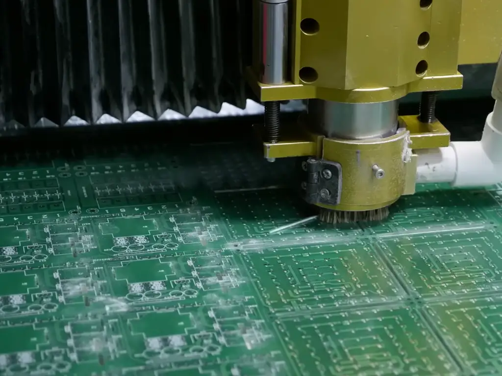
Key Assembly Steps for Rugged Industrial Electronics
Constructing a board designed for industrial use requires a careful combination of chemistry, physics, and mechanics. While the overall process flow is similar to other forms of circuit board manufacturing, additional layers of protection and validation must be implemented during the industrial process.
A typical workflow for the most reliable board assembly goes as follows:
| Step | Function | Industrial Criticality |
| 1. Solder Paste Printing | Applying solder paste to the surface of the PCB. | Precision stencils control volume to prevent shorts in high-voltage areas. |
| 2. SPI (Solder Paste Inspection) | 3D inspection of the paste deposits. | Catches volume issues before parts are placed to ensure 100% yield. |
| 3. Pick and Place | High-speed robotic placement of surface mount components. | High-pressure placement ensures parts stick during high-speed movement. |
| 4. Reflow Soldering | Heating the board in a reflow oven to melt the paste. | Customized thermal profiles prevent thermal shock to sensitive industrial ICs. |
| 5. AOI (Automated Optical Inspection) | Cameras check for skew, tombstoning, and polarity. | Verifies Class 3 solder joint quality requirements. |
| 6. THT (Through-Hole Technology) | Manual or robotic insertion of leaded parts. | Essential for heavy-duty connectors and relays. |
| 7. Wave Soldering | Soldering THT parts via a solder wave of molten solder. | Parameters adjusted to achieve 75%+ barrel fill. |
| 8. ICT / FCT Testing | Electrical and functional verification. | Simulates industrial loads to stress-test the board. |
| 10. Conformal Coating / Potting | Applying protective layers. | The final shield against the industrial environment. |
SMT and THT Mix for Mechanical Strength
In the battle of miniaturization, the consumer electronics industry has almost completely ignored through-hole technology (THT) in favor of surface mount technology (SMT) since it is faster, cheaper, and produces a smaller overall product.
That is not the case for industrial PCBA, where THT is here to stay. That’s because, for the most part, surface mount technology (SMT) components rely on the solder on the surface of the board for mechanical retention. That is, if a technician is going to be plugging and unplugging a heavy I/O connector frequently, or if a sturdy power relay is on the board, the shear force is going to pull an SMT substrate pad right off the board.
Industrial boards utilize a ‘hybrid mix’ in which we use SMT for the brain (microcontrollers, resistors) but use THT for the ‘muscle’ (connectors, relays, capacitors), where the leads of THT components go through the board, thereby mechanically anchoring themselves. This provides the structural integrity required to survive physical distress, high-current thermal cycling, and other thermal expansion.
Conformal Coating and Potting Processes
Once the components are soldered and the flux residues are cleaned, the job is not done. The board is still naked, exposed to the elements. This is where Conformal Coating and Potting come in—the armor of the industrial PCBA.
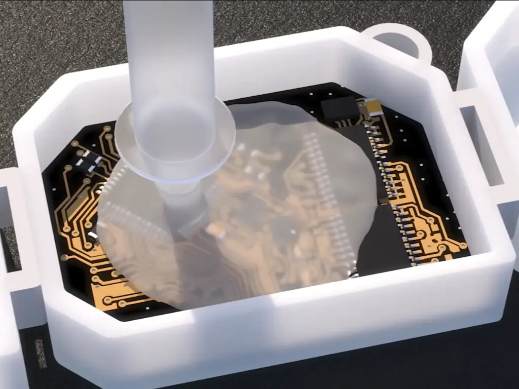
- Conformal Coating: This is a process in which a thin protective polymeric film of acrylic, silicone, or polyurethane is sprayed over the entire PCBA. The coating will act as a pseudo-skin and help prevent the circuits from being affected by water, including moisture, dust, and salt spray, chemical vapors, or other fumes. Without Conformal Coating, an unprotected board is especially vulnerable to condensation which may bridge multiple pins and short out the entire board.
- Potting (Encapsulation): For some extreme environments, the entire PCBA is placed in a potting shell case and flooded the unit with a liquid polymering compound of epoxy or silicone that cures. This makes the unit vibration and water-proof and unserviceable.
For an industrial PCBA, these are not “optional upgrades.” They are essential for survival.
Why Components are So Important for PCBA
The quality of the final product is always going to be reliant on the quality of the initial materials, despite tough inspections and orthodox assembly steps, as detailed above. A solder joint can be perfect, and the coating can be seamless, but it all will be for nothing if there is a capacitor that will fail way too early when exposed to the heat, or if a relay gets stuck shut when the voltage gets too high. In the industry, and as a rule, components cannot be just annoying little placeholders. They are the building blocks that must be able to endure the tough, reality of the environment all on their own.
Thus, the quality of the PCBA is only as good as the quality of the components. It only takes one to make a complete and complex control unit fail and become useless. This can lead to a minor saving in terms of hardware, but it will end up creating massive losses, due to downtime as well as raising operational, and maintenance, costs. This is exactly the reason we do not just focus our engineering efforts on simply “assembling” a board, but rather, we focus on “curating” its building blocks, as the selection is the first line of defense, and it will determine the board’s ultimate success or failure.
How to Select Reliable Components for Industrial PCBA
A PCBA is a system and, unfortunately, is only as strong as the weakest link in the system. It does not matter how well you make the solder joints, and how well you apply the conformal coating; the entire board can still fail if a single electrolytic capacitor dries out too early, or if a relay contact welds shut under a load. Sourcing for Industrial printed circuit board assembly requires an on the mindset: you are not selecting parts based on price; you are selecting parts based on survival. Here is a Core Industrial Components Checklist:
| Component Type | Role in PCBA | Industrial Requirement |
| Power Supplies | Converting voltage | High efficiency, over-voltage protection. |
| Relays | Switching loads | Sealed housing, high contact endurance. |
| Terminal Blocks | I/O Connection | High torque resistance, non-flammable material. |
| Capacitors | Energy Storage | High temperature (105°C+), long hour rating. |
| Microcontrollers | Processing | Wide temperature range, long-term availability. |
To ensure the longevity of your industrial equipment, each component on your Bill of Materials (BOM) should also be assessed according to three critical metrics:
Dimension 1: Environmental Resilience
The industrial environment is not forgiving. Components that are considered Commercial Grade and are rated for 0°C to 70°C are meant for office based equipment. In an unheated pump station or a control cabinet that is sitting adjacent to a furnace, a component is going to undergo thermal stresses that will result in different failure modes.
- Temperature: You should specify Industrial Grade (-40°C to +85°C) as the absolute minimum. Critical passive components like capacitors should have 105°C or even 125°C ratings.
- Physical Integrity: A range of parts such as terminal blocks and connectors are made of housing materials. Some plastics can become both brittle and deformed from either freezing conditions or high temperatures. Heavy Industrial components are designed from high-performance polyamides to retain structural integrity and ensure that wires remain clamped under extreme vibration from the environment.
Dimension 2: Electrical Derating
In the world of industrial engineering, the act of running a component at maximum rated capacity (“redlining”) is a guaranteed disaster. For reliability to be at its peak, Electrical Derating must be implemented, and that is the intentioinal selection of components with specifications well beyond what the operating conditions are likely to be.
- The 50% Rule: For example, if you have a 24V circuit, you should not have a 25V capacitor. Instead, a 50V capacitor should be used. If you have a relay that needs to switch 5 Amps, a relay rated for 10 Amps should be selected.
- Why it matters: Industrial power grids are “dirty” which means they are afflicted by voltage spikes and inductive kicks that are caused by large motors. A critical safety margin is provided by Derating. It means that for these surges to be expected for the component to handle that stress without catastrophic dielectric breakdown and thermal overload.
Dimension 3: Lifecycle Management and Availability
While consumer electronics move in 18 month cycles, the industrial market moves in decades. Designing boards around the latest and greatest chips is almost always a bad idea, as the manufacturer ends up discontinuing those chips (End of Life – EOL) 2 years later.
- The Cost of Obsolescence: If a key component becomes obsolete, you face the expensive nightmare of redesigning the PCBA, rewriting software drivers, and re-certifying the entire machine.
- The Strategy: Focus on components with a published Long-Term Availability Roadmap. Verified industrial suppliers will produce certain series for 10 to 15 years, ensuring you will be able to service your device and manufacture spare parts for years to come.
This is where the supply chain becomes your strategic partner. Finding components that meet these rigorous standards—certified, tested, and available—can be a logistical nightmare for PCBA manufacturers.
This is why industry leaders turn to OMCH.
With 38 years of manufacturing experience, OMCH provides the building blocks of reliability. Whether you need robust Switching Power Supplies with high overload capability, Relays tested for millions of cycles, or durable Terminal Blocks that withstand heavy torque, our products are engineered specifically for the factory floor. We don’t just sell parts; we provide the peace of mind that comes from ISO 9001 quality and CE/RoHS certification. When you populate your BOM with OMCH components, you are inheriting our legacy of stability and securing the lifecycle of your finished board.
Design for Manufacturing (DFM) in Industrial Applications
Reliability isn’t added; it’s built into the PCB layout. DFM revolves around incorporating your manufacturing constraints into the design, which in the industrial sector requires specific design considerations for high power and safety compliance.

The first factor involves thermal management by way of Heavy Copper. Industrial controls have high-power loads such as servo motors and heaters, which in turn generate heat along the PCB traces. A standard thin layer of copper (1oz) is often not enough, leading to current bottlenecks and hotspots that potentially delaminate the board. Industrial designs are to use 2oz and 3oz finished copper weight. The purpose of thicker copper is to act as a highly effective heatsink, spreading thermal energy across the conductive pads and internal layers allowing high current to flow without overheating.
The second factor involves signal integrity and Safety Spacing (Creepage and Clearance) because industrial environments are electrically noisy. Additionally, industrial environments often have high voltages (380V, 480V) and sensitive 5V logic co-existing on the same board. “Clearance” is the shortest distance between conductors through the air, while “Creepage” is the distance along the surface. If these two are too tight, a coincidence of a voltage spike and a layer of electrically conductive factory dust may become an arc flash, and the system is destroyed. Industrial DFM must comply with such safety standards (UL 60950 or IEC 62368) to be acceptable, which typically means manually carved safety slots have to be added into the PCB design to effectively increase the creepage distance—an uncommon safety practice for consumer electronics.
Advanced Testing Protocols for Mission-Critical Reliability
In every center of operation, quality control is an essential operation, and is not just limited to inspections. For mission-critical reliability, the best PCBA manufacturing is coupled with extensive testing procedures involving countless inspections to ensure the boards are not fielded without additional testing.
- In-Circuit Testing (ICT): The main feature of the process is the utilization of a specially designed “bed of nails” fixture to interface with predefined test points on the target assembly. It functionally isolates and examines individual components to ensure that shorts, opens, and appropriate levels of capacitance and resistance are present so that the schematic on the board is an accurate representation of the intended design.
- Functional Circuit Testing (FCT): Moving beyond simple static checks, testing involves powering the board and creating a simulation of the actual environment the board is designed to operate. Input signals are injected, and output loads are applied to ensure that the PCBA is designed to function appropriately under specified real-world conditions for the application.
- Burn-in Testing: This is the ultimate test for industrial rigidity. It involves placing powered boards into a thermal chamber (typically 40°C to 60°C) for 24 to 48 hours. This process forces “infant mortality” failures, failures that would otherwise occur in the first month of being deployed, to happen in the factory so that early field failures can be eliminated.
Selecting the Right PCBA Manufacturer for Automation
The correct partner is the last step in the journey of producing dependable industrial goods. This is not about whom the cheapest deal; it is about finding someone who will defend your quality. When assessing PCBA providers, consider the following Industrial Competence Checklist:
- Certifications: Do they hold ISO 9001? For automotive or strictly high-reliability sectors, do they have IATF 16949?
- Testing Facilities: Do they have an Aging Room / Burn-in Chamber? Ask to see it. If they don’t have one, walk away.
- Sourcing Integrity: Do they have a rigorous system to prevent counterfeit parts?
- BOM Risk Analysis: Do they offer a service to review your BOM and flag components that are nearing obsolescence?
For PCBA providers and manufacturers, sourcing industrial-grade components that are both reliable and cost-effective is a difficult balancing act. There is always the challenge of finding the accurate components that match unyielding requirements yet do not make the bill of materials jump excessively.
OMCH offers the perfect solution. We provide high-quality components that strictly adhere to rigorous industrial standards while maintaining a competitive price point. With our one-stop procurement service, we simplify your supply chain management, allowing you to consolidate orders and focus on precision assembly rather than complex sourcing.
Ready to optimize your production with trusted, affordable industrial components? Contact OMCH today to discuss your project needs.


