


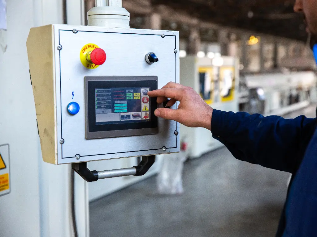
When a programmable logic controller (PLC) goes down, it radically affects automated machinery operations and can stall a company’s revenue flow. For many, the stakes and the pressure to get production running again are extremely high. In these instances, avoiding human error or operator error caused by panic is vital; it’s critical to maintain a calm and clear focus.
This guide aims to achieve this focus. Among many things, it seeks to provide a step-by-step approach to troubleshoot a PLC system, gain a rational basis to guide repair/replacement decisions, and define the characteristics of a suitable partner to engage to resume operations.
Essential PLC Troubleshooting Steps Before Calling Support
The first step is to adjust your mindset before you even open the control cabinet or pick up a multimeter. Try not to think of the PLC as a single “magic box.” Instead, think of it as a modular set of components, consisting of four functional areas: the power supply (the heart), the CPU (the brain), the I/O Modules (the hands), and the field devices (the environment). If you can mentally isolate the fault to one of the four domains, it will help to alleviate the overwhelming sense of looking at the entire industrial control systems and allow you to perform a controlled systematic triage.
Many people report PLC “failure”, which isn’t a component failure but rather environmental factors that mimic a crash. Performing the following checks can save you thousands of dollars.
1. Power and Switches
Check the obvious first. Verify the physical state of the PLC. Is the key switch on the CPU physically turned to “STOP” or “REM” (Remote)? If it was bumped during cleaning or maintenance, the program sequence simply stopped executing. Turn it to “RUN.” Next, don’t trust the cabinet light to verify power on. Use a multimeter to verify the voltage at the power supply. A tripped breaker, loose connections, or a loose terminal block can look exactly like a destroyed CPU. Be sure to check for power supply issues or voltage fluctuations that might be causing intermittent failures.
2. Decode the Error Lights
The faceplate LEDs do not behave randomly; these status indicators represent information using a primitive encoding scheme. If the “Fault” light is solid RED, it means that there is likely some sort of catastrophic hardware fault, or the watchdog timer has timed out, and the CPU has entered a locked state to prevent a sudden process stop. If it is flashing RED, it is sometimes recoverable, and can represent a mathematical overflow error based on incorrect data input or some I/O configuration is missing. Familiarizing yourself with these error codes is essential. Next, check the BATT light. If this is illuminated, do NOT power down the unit until you confirm there is a backup of the PLC program logic. A backup is necessary because if the power is cut and the battery is dead, the program in volatile RAM leads to missing data and is unrecoverable.
3. Inspect the Battery Status Immediately
For many legacy systems, and even some current platforms, there is a lithium battery that keeps the logic program alive during a power outage. If the BATT LED is illuminated, it means that battery replacement should be the highest priority to prevent permanent data loss. Important: The majority of PLCs expect you to change the battery while the power is on. If you power it off to change the battery, you will wipe the memory. This light should never be ignored. Do not consult a manual to verify its defunct status.
4. The Wiring and Terminal Integrity Check
Electronics and machinery vibrations can be very damaging. When a machine vibrates continuously over a long period, it threatens wiring integrity. Terminals and screws can loosen, causing short circuits or loose connections. To conduct a “tug test”, simply and softly pull on the wires connected to the power supply and input/output cards. Also, if a neutral wire is loose, it can cause power interruptions by cycling power to the system, creating the appearance of a malfunctioning CPU. Furthermore, look for corrosion, especially of terminals. Corroding terminals create resistance and heat that can lead to a sudden drop in system voltage.
Common PLC Failure Modes and Electrical Causes
If the problem persists after going through the basic checks, we will have to go deeper to understand why PLC control systems fail. PLCs, while designed for severe conditions, are still electronics containing sensitive components, and can be quite sensitive. It is crucial to understand the common reasons they fail to prevent recurrence.
Power Supply Module Failures and Voltage Spikes
Power Supply Modules (PSMs) must deal with the most challenging tasks in the control cabinet. The job of the PSM is to convert dirty line voltage (120VAC or 24VDC) from various electrical sources to the clear 5VDC needed by the CPU and the logic circuits. The PSM doesn’t operate by design; it malfunctions. The most common reason for power supply module failures is dirty power; specifically, electrical problems in the form of a power surge and voltage fluctuations from the grid or from large starting motors in the vicinity.
Power supplies contain special capacitors called electrolytics, which act as banks to store energy. With heat and age, the caps in PSMs will always dry out. Power supplies can store significant energy and if undersized components (exposed to heat and age) get a major voltage spike, the input protection circuitry can be tripped. The power supply that shorts will not explode. However, the voltage will drop to, say, 4.5V. This will not fry the CPU, but it will cause logic amnesia. This is the phenomenon where the CPU has glitches, it loses its communication, or it reboots for no apparent reason, leading to unpredictable behavior and unreliable operation, where no software can help to troubleshoot the mess.
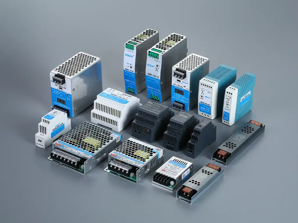
The stability of your PLC hinges on high-quality components. If the power supply fails, the only reliable course is prompt replacement. As a manufacturer, OMCH views the power supply as the most critical protection device. Our ISO 9001-certified industrial power supplies ensure steady performance and feature comprehensive safety—including short circuit and surge protection—to shield your entire control system from future electrical volatility.
I/O Module Burnout and Grounding Issues
Input devices and output modules serve as an interface between the digital and physical and therefore are the most exposed to electrical stress from the outside world. One of the most common failures is due to Inductive Kickback affecting output devices. When the PLC output shuts off a solenoid valve or a motor contactor, the coil’s magnetic field collapses and a high voltage (back EMF) is generated and spikes toward the PLC card.
If unprotected, this phenomenon will happen thousands of times a day and will eventually char the output transistor, leading to module failure or causing unresponsive sensors. Additionally, verify proper grounding to avoid grounding issues. If the PLC and a remote sensor are grounded at different points, ground loops occur. These ground loop effects create a current flow using the signal wire. This noise will cause the PLC to read the signal incorrectly (it might read a ‘1’ as a ‘0’), or the noise will burn the small traces of thin circuit boards. This will lead to instant and irreversible channel loss.
CPU Corruption and Battery Dependencies
In general, the central processing unit (CPU) is the most powerful and versatile unit; however, the failures are usually the most damaging. As with any other battery-operated system, the PLC control module is liable to lose all functioning memory. Moreover, the CPU is very susceptible to electrical noise and overheating. Strong external interference from Variable Frequency Drives (VFDs) or welding equipment can cause electromagnetic interference (EMI) or radio frequency interference. This electrical noise interference can induce rogue currents in communication cables, dropping packets and causing “Processor Faults,” software glitches, or even total software corruption.
Moreover, the thermal management is paramount. Industrial environments often present environmental factors such as dust and high temperatures. If cabinet cooling fans fail, heat accumulates. Electronics degrade exponentially with heat. A CPU running in extreme temperatures (e.g., 10°C hotter than specification) will have its operational life cut to 50%, while thermal damage to internal bonding wires will incur unrecoverable CPU corruption. At this point, the CPU becomes untrustworthy and must be removed from the enclosure.
Proactive Protection Strategies to Prevent Future Failures
Once a system is repaired, the target becomes permanent, wherein you do not fix the same problem twice. Repair shouldn’t be the norm; regular electrical maintenance is key. Ensuring the system’s health requires mitigation that is not an afterthought. The following table describes specific techniques, including surge protection and the use of isolation transformers, aimed at armouring your control system.
| Vulnerability | Root Cause | Protection Strategy | Implementation Action |
| Power Surge & Transients | Lightning strikes, grid switching, or large load switching on the factory floor. | Surge Suppression (SPD) | Install a dedicated Surge Protection Device (SPD) at the main power entry of the control cabinet. This acts as a gatekeeper, diverting excess energy to the ground before it reaches the PLC. |
| Voltage Fluctuation | Regularly clean air filters on cabinet fans. If the ambient temperature exceeds 40°C, install an enclosure air conditioner. Ensure the PLC rack has adequate clearance above and below for natural convection. | Regulated Power Supply | Upgrade to a high-quality Industrial Switching Power Supply. Look for units with wide input voltage ranges and active power factor correction (PFC) to ensure stable DC output even when AC input fluctuates. |
| Inductive Kickback | Back EMF generated when switching off solenoids, contactors, or relays. | Isolation & Suppression | Install Intermediate Relays between the PLC output and the heavy load. This ensures the cheap relay burns out instead of the expensive PLC card. Also, install RC snubbers or diodes across inductive coils. |
| Signal Noise (EMI/RFI) | Electrical noise from VFDs or welders coupling into signal lines. | Shielding & Routing | Use shielded twisted-pair cables for analog signals. Route low-voltage DC cables in separate wire ducts from high-voltage AC cables. Ensure all shields are grounded at one end only. |
| Thermal Overload | High ambient temperature or blocked airflow in the cabinet. | Cabinet Climate Control | Regularly clean air filters on cabinet fans. If ambient temperature exceeds 40°C, install an enclosure air conditioner. Ensure the PLC rack has adequate clearance above and below for natural convection. |
Cost Analysis: Repairing PLCs vs. System Replacement
When system failures occur, it is a binary decision: repair the old PLC or upgrade to a new one. This is a critical financial decision requiring an ROI calculation. Are PLC repair services the most effective ways to spend your budget?
A standard repair, according to the industry, will cost anywhere from 20%-40% of the price of a new one. The industry also has a standard, the 50% Rule. This Rule says, if you think repair services will cost 50%-60% of replacement, you should always replace it to get the increased lifespan and added warranty.
The entire situation changes dramatically if a part is considered “Obsolete” or “End of Life.” If you can’t purchase a new one, your options are high-risk surplus/used or, what we call a professional repair. A qualified maintenance service provider can offer a “professional repair” that essentially resets the clock on the hardware.
Also, don’t forget the hidden engineering cost of replacement. The software also needs to be rewritten and retested, which is required to replace an old unit on a new platform and is often a cost that overshadows the hardware. Addressing various issues via an $800 repair that has “Plug and Play” installation is often smarter than a $500 replacement that incurs $5,000 in engineering time.
Understanding the Professional Component-Level Repair Process
Is it possible for your site’s electrician to just solder a new capacitor onto the board? Why is professional service needed? The difference is finding the true root cause and the root of the problem. In a DIY repair, the professional refurbishment process is done in a repair clinic.
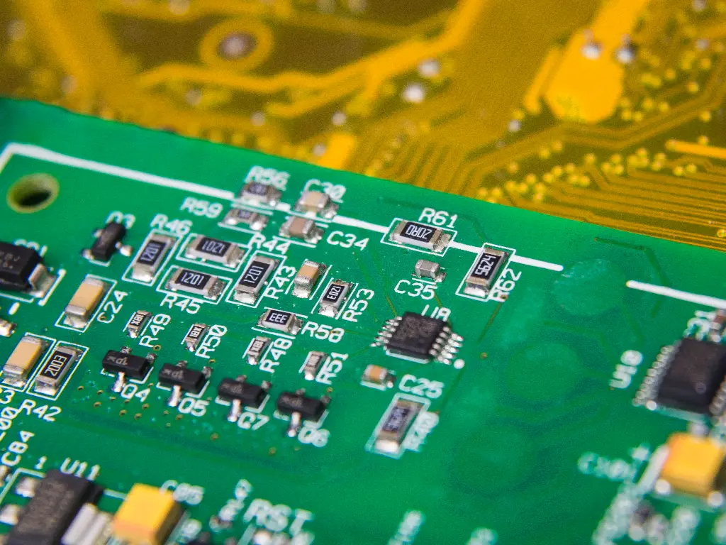
- Ultrasonic Cleaning
Visible contaminants on industrial circuit boards, as well as burnt carbon dust and conductive chemicals. Conductive residue can short circuit your circuit board. Professional shops immerse boards in ultrasonic cleaners using electronics-safe solvents.
- Signature Analysis and Component Testing
Burns are easy to miss, so technicians don’t just analyze visually. They use logical signature analysis repositioning devices to probe chips for passive testing. They test capacitors for Equivalent Series Resistance (ESR). A capacitor may look physically perfect. We filter the voltage, then burn it out.
- Profiling and BGA Rework
Modern PLCs use Ball Grid Array (BGA) chips, which have hundreds of contacts on the bottom surface. It is impossible to hand solder these. Infrared rework stations are professional grade equipment, and these are tapes are to level microscopic precision, lift and replace processors.
- The Crucial Step: Load Testing
This is where DIY repairs fail. A PLC output can easily trigger an LED on a workbench. However, when it is called to control a 2-amp solenoid valve, it may fail due to fragile internal drivers. Professional shops apply what are called dynamic load banks. These are used to run the repaired PLCs with a sustained electrical load as might be found in a real factory, sometimes for 24 to 48 hours. This burn-in process detects infant mortality failures while the unit is still in the professional shop rather than after it has been sent back to the user’s facility.
Criteria for Selecting a Reliable PLC Repair Provider
Not all PLC repair services are created equal. The barrier to entry is low, but the barrier to excellence is high. When vetting a maintenance service provider to handle your critical automation assets, look for these three non-negotiable criteria:
- The warranty structure: A warranty of at least 12 months is the minimum acceptable warranty. A shop that has only a 90-day warranty has very little faith in its workmanship.
- Active Test Rigs: Ask them in particular: “Do you have a rack and CPU to test my exact model?” There are many brokers who claim to be repair shops, but in fact, they outsource all the work. No test stand means no knowledge.
- Rush Capability: Days off can be costly. A good partner for your company should be able to provide a ‘Rush’ option in 24-48 hours for your urgent requests.
Considering these criteria, the following table provides a quick comparative analysis of these reputable companies.
| Provider | Primary Strength | Ideal For | Warranty Standards |
| Radwell International | Massive inventory of surplus and obsolete parts. | Finding replacements for “End of Life” equipment. | Typically 2 Years |
| Schneider Electric Repair | Official OEM authority and factory specs. | Current Schneider/Modicon hardware requiring certified repair. | 1 Year (Factory Standard) |
| AES International | Deep technical expertise in board-level repair. | Complex repairs where no replacement exists. | 2 Years |
Final Thoughts on Maximizing Industrial Equipment Uptime
Regardless of the damage, repairs will always be required. But this is the ‘ambulance’ approach after you’ve gone over a cliff. Ultimately, each PLC failure indicates a concerning reality: your control environment remains highly unstable. You can continue to repair the damage caused by other repairs, or you can mitigate these failures by strengthening your cabinet system to withstand the electrical noise, heat, and power surges that will obliterate fragile components.
As a manufacturer with 38 years of production experience, we have come to appreciate the difficulties of working with a factory environment. Our commitment to providing stable industrial components remains steadfast. With over 72,000 customers in 100 countries, we have a wealth of knowledge from different industries to help us build a complete factory understanding. Our 20+ years of experience engineers are eager to assist you to locate the most precise and professional solutions for your automation problems.
Don’t wait for the next breakdown. Provide your systems with the clean power and signal isolation they deserve. Explore the OMCH Catalogue today to find the industrial power supplies, relays, and protection components that turn a fragile system into a fortress.


