In the world of electrical engineering and industrial automation, everything boils down to a binary choice: is the circuit on, or is it off? This may sound easy, but it is the reasoning behind getting there, and it is what happens when the machine malfunctions that is what makes the difference between a factory that runs smoothly and a catastrophic safety failure.
This brings us to the fundamental concepts of Normally Open (NO) and Normally Closed (NC). Whether you are a student wiring your first relay or an experienced engineer developing a complicated PLC (Programmable Logic Controller) architecture, you must learn the ins and outs of normally closed vs normally open logic. This guide will take you through the technical principles, fail safe principles and working selection principles so that your electrical circuits are efficient and safe.
Defining NO and NC: Understanding the “Resting State”
We must know what is meant by a “normal” position in an electrical context to know what NO and NC are. Essentially, it can be said that to understand what is normally open and normally closed, one needs to look at the default position, the de-energized position or the rest position of a part. Properly identifying this default state is essential for predicting how a system will behave during a complete power loss. This is the state of the device when it is on a shelf, or when it is not subjected to any external force (physical, electrical, and magnetic).
- Normally Open (NO): In its resting state, the electrical contacts are physically separated. The circuit is “open,” meaning no current can flow. This physical gap remains until a specific mechanical action, such as the pressing of a button or the movement of a lever, forces the contacts together. Consider a drawbridge which is initially in the up position, cars cannot cross until an operator (the trigger) drops the bridge (closed the circuit).
- Normally Closed (NC): In its resting state, the electrical contacts are physically touching. This leads to closed circuits and current flows freely. It is a bridge that is closed by default, in our bridge analogy, the traffic is utilizing the bridge until an operator raises the bridge (opens the circuit) to halt the traffic.
Think of a standard spring-loaded pushbutton or a simple light switch. Normally Open buttons make you press to complete the circuit (such as a doorbell). The circuit is already closed by a normally closed switch, and when it is pressed, the connection is opened (as in the case of the “Stop” button of a conveyor belt).

Normally Open vs Normally Closed: Key Functional Differences
Although the fundamental definitions are straightforward, the way the system behaves when it is running and when it is powerless is determined by the major distinctions in the functional logic of these two modes. The decision of NO or NC is not a random decision but a calculated decision based on what the machine wishes to do with defaulting.
The comparison of the two states in terms of technicality is as follows:
| Feature | Normally Open (NO) | Normally Closed (NC) |
| Resting State | Circuit is Open (No Continuity) | Circuit is Closed (Continuity) |
| Trigger Action | Closes the circuit (“Makes” contact) | Opens the circuit (“Breaks” contact) |
| Electrical Symbol | Gap between two lines/circles | A diagonal line connecting two points |
| Power Consumption | Consumes power only when active | Consumes power to stay “Open” (if using a relay) |
| Fail-State Signal | Loss of power results in an Open state | Loss of power results in a Closed state |
| Primary Use | Start/Run signals, general logic | Safety stops, limit detection, alarms |
The terms of Make and Break are frequently used in industrial catalogues. When ordering a certain part number with foreign manufacturers, one should know these standard nomenclatures an NO contact is commonly referred to as a “Form A” contact and an NC contact is referred to as a “Form B” contact.
Beyond Basic Switches: Understanding SPDT and DPDT Logic
In many advanced applications, a simple two-terminal NO or NC switch isn’t enough. We often encounter components which can handle either of these two conditions simultaneously or components which can handle multiple circuits. Here we have to do with the “Pole” and “Throw” terminology.
- SPDT (Single Pole Double Throw): This component has one common (COM) terminal and two output terminals: one NO and one NC. It acts as a “changeover” switch. When the switch is on rest the COM is connected to the NC terminal. When triggered, the COM flips to the NO side. This can be best used with status indicators (e.g. a green light to indicate “Running” and a red light to indicate “Stopped”).
- DPDT (Double Pole Double Throw): Imagine two SPDT switches glued together and operated by a single trigger. This enables you to operate two independent circuits (poles) at the same time each having its own NO and NC outputs.
The type of switch you select—whether SPDT or DPDT—is standard in high-quality industrial relays. They enable engineers to generate complex interlocking logics without extra components and save a lot of control panel space.
The Fail-Safe Logic: Why Safety Circuits Prioritize NC

Probably this is the most important part of this guide about safety systems. In engineering, a “Fail-Safe” design is a design where a component fails (either the power supply or the wiring itself) the system is designed so that it can gracefully degrade to a non-hazardous state.
Why is NC the gold standard for safety? The core principle is “Wire-Break Monitoring.” Imagine an Emergency Stop (E-Stop) button. If you use a Normally Open (NO) contact for an E-Stop, the circuit only sends a “Stop” signal when the button is pressed. However, what happens when a wire in the E-Stop circuit is accidentally cut, vibrated off or chewed up by a rodent? The controller in an NO setup would interpret an open circuit and believe that all was “Normal.” Once a worker presses the button during the emergency, the signal path is already destroyed, and the machine does not stop. This is a “Fail-to-Danger” scenario.
Conversely, if you use a normally closed switch for the E-Stop, the circuit is constantly “proving” its integrity by sending a continuous “Safe” signal to the controller. If a wire is severed, the flow of electricity stops immediately. This loss of continuity is detected by the controller as a “Stop” command and an emergency shutdown is triggered. In this case, the system fails to a safe state.
Advanced Insight: The Short-Circuit Limitation Although NC is better at identifying open circuits, a step further is taken in the field of safety design that is truly professional. A normal normally closed switch may be defeated by crushing the two wires in the cable together (a short circuit), which would still be regarded as a closed circuit by the controller even when the button is released. To combat this in high-risk environments, engineers implement dual-channel NC circuits or monitored loops with end-of-line resistors. These systems are able to differentiate a fault (short or break) and a healthy, so-called, “Safe” state, which is the most secure available in modern automation.
Pro Tip: Always use NC contacts for safety-critical inputs like Emergency Stops, Light Curtains, and Over-travel Limit Switches. Use NO contacts only for non-critical “Start” or “Initiate” commands where a failure to start is a nuisance, not a hazard.
Real-World Applications: From Home Appliances to Industrial Sensors
Understanding the theory is one thing, but seeing it in action is essential to truly grasp the logic behind these systems. It is important to remember that these concepts apply to fluid dynamics as well; for example, normally open valves are frequently used in irrigation or cooling systems to allow flow until a control signal is sent to close them.
- Consumer Electronics
- Refrigerator Door: This is a classic Normally Closed application. The switch is held open (light off) by the door itself. Upon opening the door, the pressure is relieved, the switch is switched back to its closed position of the “Normal” position and the light is switched on.
- Doorbell: A Normally Open switch. The chime is intended to be heard only when the button is actively pressed.
- Industrial Automation
- Proximity Sensors: These are required to ascertain the existence of objects on a conveyor. An NO proximity sensor will not provide any signal until an object is detected. An NC proximity sensor will give a steady signal and break when an object is sensed-usually used to sense gaps in a line.

- 4-Wire Configurations: In heavy industry, proximity sensors—including both inductive and capacitive types—frequently utilize 4-wire configurations that provide both NO and NC outputs (NO+NC). This enables the engineers to have a single signal to regulate the main logic and the other one to possess an independent monitoring system or redundancy check.
- Pressure Switches: An air compressor has a pressure switch that is an NC pressure switch that keeps the motor running until a set pressure is reached in the tank, at which point the switch opens and the motor is turned off.
Bridging the Gap: Physical Contacts vs. PLC Logic
A common point of confusion for those transitioning from hard-wired relays to PLC programming is the interaction between physical hardware and software instructions.
In a PLC, you have two primary input instructions:
- XIC (Examine if Closed): Often represented as a symbol that looks like an NO contact.
- XIO (Examine if Open): Often represented as a symbol that looks like an NC contact.
The “Double Negative” Trap:
If you wire a physical Normally Closed E-Stop button to a PLC input, the input bit in the PLC memory will be “1” (High) when the button is NOT pressed.
- If you use an XIC instruction in your code, the instruction will be “True” because the physical contact is closed.
- Many beginners mistakenly use an XIO instruction because the button is a “Normally Closed” type. But when an XIO instruction is used on a closed contact it results in a “False” state in the software logic.
Essentially, you must remember that the PLC instruction “looks” at the status of the terminal. If a physical NC switch is used for safety, the PLC code should usually treat the “presence of voltage” as the “Safe” condition.
Selection Criteria: How to Choose the Right Configuration
The decision between NO and NC (or both) is not only a matter of logic, but also reliability, power consumption, and finding the appropriate partner to make the system brain work perfectly with time. The technical factors to be considered when choosing components include the following factors in addition to the infrastructure of the manufacturer:
- Safety and Compliance First: In case a component failure may lead to a hazard, a priority should be given to NC in monitoring wire-breaks. To ensure this safety, it is important to procure components that are of international standards like IEC standards, CCC, CE and RoHS standards. Partnering with an established manufacturer like OMCH (founded in 1986) ensures that these certifications are backed by decades of R&D and a global footprint serving over 72,000 customers in 100+ countries.
- Optimizing Duty Cycle and Lifespan: When a switch remains inactive 99% of the time, an NO configuration is often preferred to prevent relay coils from being constantly energized, which reduces heat and extends device life. In order to reach such accuracy, engineers must have a large portfolio, like the 3,000+ SKUs available at OMCH, to locate the precise electrical match to the duty cycle of their machine.
- Environmental Integrity and Quality Control: The industrial sensors should be able to remain in their “Normal” state even when subjected to high vibration or moisture, which demands high IP ratings such as IP67. To accomplish this consistency, a manufacturer whose ISO9001 quality systems are integrated and has more than one production line (OMCH has 7) must be able to guarantee that all sensors, including inductive and photoelectric, are of the same high quality.
- EcosystemCompatibility (One-Stop Sourcing): An ecosystem is not a set of independent components, but a fail-safe system. To ensure the highest level of reliability, the sensors (proximity/light curtains), control elements (relays/counters), power supplies (DIN Rail), and protective equipment (circuit breakers) are to be designed to interact. Using a full vendor can guarantee a smooth flow of the whole control loop.
Finally, your NO/NC states are as reliable as the support that they have. A one-year warranty and 24/7 technical response is a solution that guarantees that your “Normal” state will be normal during the life of the machine.
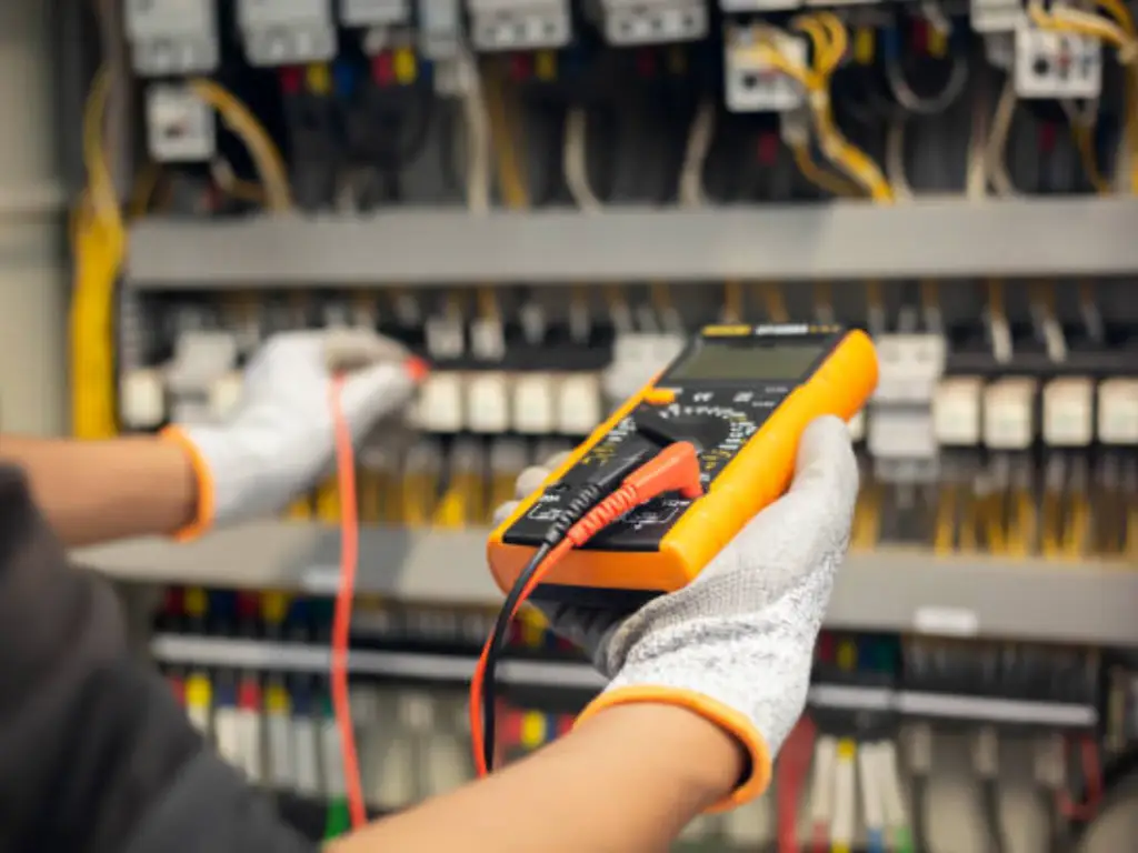
Troubleshooting Guide: Testing Contacts with a Multimeter
A switch will eventually break, or a label will eventually be worn off. The ability to recognize NO and NC contacts in the field fast is a required skill of any technician.
Step 1: Safety First
Ensure the circuit is de-energized. Never test for continuity on a live circuit, as this can damage your multimeter and pose a safety risk to you.
Step 2: Set the Multimeter
Turn your digital multimeter (DMM) to the Continuity setting (usually indicated by a sound wave or diode symbol). When the meter is set to this continuity mode, it provides a quick audible confirmation of whether an electrical path is complete. Touch the two probes together; you should hear a continuous “beep,” indicating a closed path.
Step 3: Test the Resting State
Connect the probes to the terminals of the switch or sensor while it is at rest.
- If it beeps: You have found a Normally Closed (NC) contact.
- If it remains silent: You have found a Normally Open (NO) contact.
Step 4: Test the Triggered State
When the probes are connected, press the switch (press the button, trip the limit or place an object in front of the sensor) manually.
- The NO contact should now beep.
- The NC contact should now go silent.
Step 5: Check for High Resistance
If you get a beep but the screen shows a high resistance (more than a few ohms), the contacts may be pitted or oxidized. This is a common failure mode in industrial environments, and the component should be replaced to prevent intermittent logic errors.
By mastering the balance between Normally Open and Normally Closed logic, you aren’t just connecting wires—you are architecting the reliability and safety of the modern industrial world. Whether you’re integrating a high-precision industrial sensor or wiring a master E-Stop, always design with the “Fail-Safe” in mind to ensure that your system protects both equipment and personnel under any failure condition.