


The industrial control panel takes a central place in the architecture of industrial production. It is the controlling agent of industrial equipment, the localized location where electrical potential is transformed into kinetic work and rational decision-making. An electrical control panel can seem to the uninformed as a simple box of wires and flickering lights. But in terms of engineering and systems, it is a highly hierarchical environment that is meant to deal with complexity, safety, and efficiency.
Knowing the parts in this enclosure is not merely a question of memorizing a parts list. It involves a valuation of the functional interrelationships of power distribution, protection, logic, and execution. This paper examines these key elements, including their respective functions and how they are chosen.
To assist in navigating this complex architecture, the following table summarizes the critical components discussed and their pivotal selection criteria:
| Device | Primary Function | Critical Selection Criterion |
| Enclosure | Environmental shielding | IP Rating (e.g., IP65 for washdown) |
| Ind. Power Supply | AC to DC Rectification | Derating Curve & Power Headroom |
| Circuit Breaker | Overcurrent interruption | SCCR (Short Circuit Current Rating) |
| SPD | Transient voltage suppression | Response Time & Surge Capacity |
| PLC | Process control & logic | I/O Capacity & Environmental Hardening |
| Solid State Relay | High-frequency switching | Duty Cycle & Thermal Dissipation |
| VFD | Precision speed control | Application Type (Variable vs. Constant Torque) |
| Terminal Block | Secure wiring interface | Vibration Resistance (e.g., Spring-cage) |
What is an Industrial Control Panel?
An industrial control panel is a group of electrical parts that measures and regulates the mechanical operations of heavy equipment or industrial processes in various industrial settings. In case we were to use a biological analogy, the control panel would be the “Brain” and the “Central Nervous System” of the industrial body. The control system controls the flow of information and energy through the system just as the nervous system receives sensory input, processes it, and orders the muscles to move. The basic functionality of any control panel is linear and three-stage:
- Input (Acquisition): The system gathers data from the field. This involves devices such as sensors, switches, and input signals from push buttons sending data back to the panel.
- Logic (Processing): The central controller, typically a Programmable Logic Controller (PLC), interprets these signals based on pre-programmed algorithms. It decides what action is required.
- Output (Execution): The controller sends commands to execution devices—such as motor starters, relays, or HMI displays—to alter the state of the machine.
Although the internal components tend to overlap, the structure of a panel is determined by its main purpose. Understanding the different types of industrial control panels is crucial for selecting the right solution for a common application. The most common applications are compared in the following table:
| Panel Type | Primary Function | Typical Application Scenario |
| Motor Control Center (MCC) | High-power distribution and control. | Used in facilities where the primary task is driving large motors, such as water treatment plants or conveyor systems. |
| PLC Control Panel | Logic processing and automation. | The standard for modern control panels in automation systems for assembly lines, robotics, and complex machinery requiring precise sequencing. |
| HMI Station | Interface and visualization. | Located near the operator, this panel houses the screen and manual controls, allowing human oversight of the system status. |
Structural Foundations: Enclosures and Back Panels
The physical environment should be taken into consideration before dealing with the electronics. The enclosure gives the structural integrity and environmental protection required to make the control panel components work. The choice of this shell is a risk management exercise, which protects delicate electronics against certain environmental factors like dust, oil, or corrosive chemicals. The IEC 60529 standard classifies protection levels globally in terms of IP (Ingress Protection) ratings. IP54 is the standard of general indoor use, which prevents short circuits due to airborne debris or accidental splashes. In more extreme conditions, IP65 (dust-tight and low-pressure water jets) or IP66 (high-pressure jets) are mandatory.
Metal enclosures, often made of stainless steel for corrosion resistance, are the industry standard. After the exterior protection is in place, the internal architecture is based on the Back Panel and DIN rail. The back panel serves as the stiff backbone on which the panel components are mounted, and the din rail—a standardized metal strip—is used to allow the modular mounting of circuit breakers, terminals, and power supplies. This standardization is essential to efficiency, making the assembly process support a modular design. In defining these dimensions, space should be considered as an asset that has option value. Always ensure sufficient space—leaving 20-30 percent of additional space on the back panel and DIN rails.
Power Distribution: Transformers and Power Supplies
Electrical power is fed into the panel at high voltage (typically 480 V or 230 V AC) but needs to be used at lower, safer voltages to drive control logic. This transformation and dissemination is controlled by power distribution components.
Main Disconnect Switch
The Main Disconnect is the point of entry of energy. It is a mechanical safety switch that isolates the panel with the grid. Its main purpose is the safety of personnel, which is to physically disconnect power prior to any maintenance. The majority of disconnects have a mechanical interlock that does not allow the panel door to be opened when the power is on.
Power Distribution Blocks
Power that has passed the disconnect is fed into Power Distribution Blocks. These elements act as the splitter mechanism. They receive large-gauge incoming cables and separate the main current into different smaller branch circuits, supplying the motor controllers and the power supplies independently.
Transformers
An industrial control panel transformer is used to reduce high AC voltages (e.g., 480 V or 230 V AC) to standard control voltages (usually 120 V AC). Although less popular in current low-voltage DC layouts, they are essential in driving AC contactor coils or convenience outlets on the panel.
Industrial Power Supplies
Contemporary automation systems are based on Direct Current (DC). This requires the application of the Industrial Power Supply, which is a device that rectifies high-voltage AC to a stabilized low-voltage output, usually DC voltage (24V DC). This unit serves as the power source of the control logic, supplying such vital elements as PLCs, field sensors, and HMIs. Here stability is of the utmost importance; any slight variation in the power supply can be transmitted through the system, leading to unpredictable actions of logic controllers or sensor readings.
The choice of power supply is not just a matter of matching voltage requirements, but involves a load dynamics and energy management calculation:
- Power Headroom: An engineer must never design a power supply to operate at 100 percent of its rated power. Working at full capacity creates too much heat and reduces the life of the components. A 20-30% headroom is a safe margin that will guarantee longevity.
- Derating Curves: The efficiency of power supply is negatively proportional to temperature. A unit marked 10 Amps at 20 o C can only produce 7 Amps at 60 o C. It is necessary to refer to the derating curve of the manufacturer to make sure that the unit is capable of supporting the load in the hot interior of an enclosure.
- Input Voltage Range: Industrial power grids are prone to variations. A strong power supply should be able to take a large input range (e.g., 85VAC to 264VAC) to keep the output constant during sags or power surges in the power of the facility.
Circuit Protection Devices
There is always the possibility of disastrous failure in any electrical system. Equipment may be destroyed by short circuits and overloads, and lead to fire. The insurance policy of the control panel relies on circuit components and electrical devices acting as a crucial safety device.
Circuit Breakers (MCB and MCCB)
Circuit Breakers act as resettable switches that automatically interrupt current flow when a fault is detected.
- MCB (Miniature Circuit Breakers): These are typically used for lower-current branch circuits, such as protecting electrical circuits for a power supply or a specific control string.
- MCCB (Molded Case Circuit Breakers): These are sturdier devices that are utilized in larger current main distribution, and can interrupt large fault energy by electrical faults.
Fuses
Fuses differ from breakers in that they are sacrificial components. While they must be replaced after a fault, such as an open circuit event, they often provide faster reaction times than breakers. This characteristic makes them ideal for protecting highly sensitive electronics, such as Variable Frequency Drives (VFDs), which can be damaged by energy spikes faster than a mechanical breaker can trip.
Surge Protection Devices (SPDs)
Although breakers are used to manage current, a very common fact that is not considered is the protection against transient voltages. The shield against these invisible spikes is the Surge Protecting Devices (SPDs). A voltage spike could have been insignificant in the days of the old electromechanical relays. Microprocessors (PLCs, HMIs) are now used in control panels operating on sensitive logic levels (24V DC). Even a lightning strike on the grid, or the inductive kickback of a large motor starting nearby, can cause a transient that can fry these logic circuits in an instant. The SPD is an obligatory investment in a modern manufacturing setting where data integrity is the key factor to avoid hardware destruction from power surges.
Logic Control Systems: PLCs and Relays
Programmable Logic Controllers (PLCs)
The PLC is the logic processor that is predominant in industrial automation. It is a hardened computer that can perform complex instruction sets, timing, counting and communication protocols. A PLC, in contrast to a typical PC, is built to resist vibration, noise, and temperature extremes, and runs in real-time to manage machine conditions.
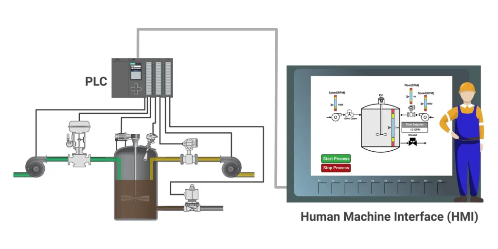
Human Machine Interfaces (HMIs)
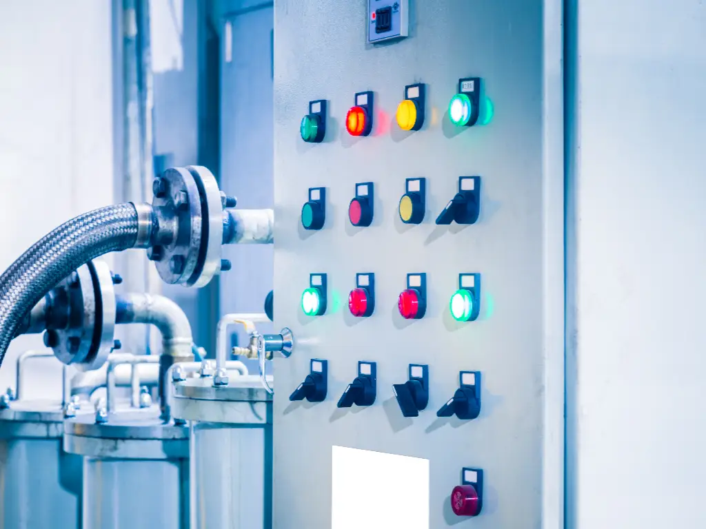
The PLC is the hidden brain whereas the HMI (Human Machine Interface) is the face of the machine. It substitutes the old physical pilot lights and push button rows with a dynamic digital touchscreen. This enables operators to see the health of the system, monitor production information, and manipulate parameters in real-time. This serves as the critical communication link between the human operator and the automated logic, often integrating with SCADA systems.
Relays (General Purpose)
The role of relays is much more basic, but equally important: signal isolation and interposing. An example is a PLC can generate a low power 24 V DC signal, yet the device to be actuated is a 120 V AC fan. A relay fills this gap, where the low-voltage signal is used to switch the high-voltage circuit without subjecting the PLC to the increased energy.A typical design choice is the type of relay to use to switch the high-voltage circuit.
- Electromechanical Relays (EMRs): These use a physical magnetic coil to close a metal contact. They are cost-effective and robust for general use.
- Solid State Relays (SSRs): These use semiconductors to switch the load. They have no moving parts.
The decision will be based on the duty cycle of the application. Assuming that a heater must switch on and off every 5 seconds to keep the temperature at the correct level, an electromechanical relay would fail mechanically in a few weeks because of contact wear. With no moving parts, an SSR is capable of indefinitely switching at high frequencies. Thus, in high-speed or high-cycle applications, the solid-state solution is the only cost-effective solution.
Motor Control Devices: Contactors, VFDs, and Soft Starters
s information is processed by logic systems, the physical work is done by motor controllers and motor drives. They handle the large electrical loads needed to power electric motors.
Contactors
Contactors are simply heavy duty relays that are used to accommodate the high inrush currents of motors. They offer easy across-the-line starting–the motor starter is either on or off. They are the cheapest when it comes to constant speed motors that do not need to be started frequently.
Variable Frequency Drives (VFDs)
Variable Frequency Drives (VFDs) are used to regulate the motor speed and torque of the motor by changing the frequency of the power supplied. They are also necessary in processes that need high accuracy like a conveyor belt that needs to slow down when weighing a product. Moreover, VFDs are very energy efficient because they can operate the motors at slower speeds when they do not need to operate at full power.
Soft Starters
Soft Starters are created to address a particular issue: mechanical shock. They momentarily lower electrical current and voltage when starting to slow up the motor. This helps avoid the abrupt jerk which may break belts or strip gears, prolonging the mechanical life of the equipment. The versatility of VFDs usually causes engineers to default to them, yet this is usually an inefficient use of capital. A Soft Starter is better when the application such as a water pump or fan needs to run at a fixed speed. It is cheaper, physically smaller, and produces fewer electrical harmonics compared to a VFD. Choose the component that is appropriate to the complexity of the task.
Connectivity Interface and Wiring for Field Sensors
The usefulness of a control panel is defined by its capability to be connected with various sources from the outside world. The physical layer of this integration is the connectivity interface connecting various components.
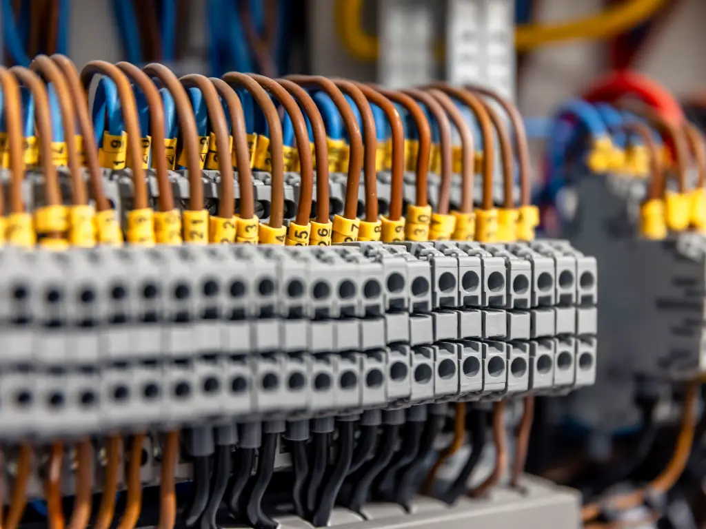
Terminal Blocks
Terminal Blocks are the structured points of connection between field wiring and internal panel wiring. The blocks are of high quality, like spring-cage terminals, which makes sure that the connections are not lost during the vibration of industrial machines, and the signal is not lost occasionally.
Wire Ducts
The slotted plastic channels that carry electrical wires through the panel are called Wire Ducts. They handle the mess of cabling, keep the air flowing to cool, and keep the panel in order. Circuit tracing requires a structured wire layout to help in troubleshooting.
Marking Systems
Marking Systems (labels on wires and terminals) are important to maintenance. The value of these elements is achieved at the maintenance stage. The panel is not well organized and marked, which adds to the Mean Time To Repair (MTTR) greatly. The clear identification will make sure that the complicated logic of the PLC is correctly relayed to the field sensors and actuators without error.
Strategic Component Selection for Reliability and Efficiency
Control panel design is an optimization problem. The goal is to achieve maximum equipment safety, system reliability, and life and reduce the overall cost of ownership. This cost is not just the Bill of Materials (BOM) but also the procurement costs, time spent on control panel assembly, and maintenance procedures in the future.
The supply chain can easily become inefficient when the engineers are sourcing the components in a disjointed list of suppliers- sensors with one, power supplies with another, relays with another. This increases administrative friction and the risk of compatibility issues.
A rational approach to component selection involves consolidating procurement with a comprehensive manufacturer. OMCH exemplifies this integrated model. As a specialized manufacturer of industrial automation controls, OMCH provides a unified source for the critical ecosystem of the panel—ranging from Industrial Power Supplies and Solid State Relays to Contactors and field Sensors.
By sourcing from a manufacturer with over 37 years of experience and adherence to CE, RoHS, and CCC certifications, engineers can ensure consistency in quality across the entire control chain. This vertical integration simplifies supply chain management and ensures that the components are engineered to function cohesively.Visit our catalog to view our one-stop solutions for power, protection, and control.


