












Apa Itu Blok Terminal Rel DIN dan Bagaimana Cara Kerjanya
Setiap kabinet kontrol yang dibangun, dirawat, atau dimodifikasi oleh pelanggan Anda berisi deretan konektor modular ini. Blok terminal rel DIN adalah wadah plastik ringkas yang dipasang dengan cara dijepit pada rel pemasangan logam standar berukuran 35 mm, sehingga membentuk sambungan kabel yang teratur sebagai pengganti kabel-kabel yang kusut pada strip terminal sekrup tradisional. Bayangkan saja sebagai Lego industri: rel DIN adalah papan dasarnya, dan setiap blok terminal adalah balok pembangunnya — yang dapat dipasang dengan dijepit, digeser ke posisinya, atau dilepas tanpa alat. Bagi grosir dan distributor peralatan listrik, produk ini merupakan barang habis pakai dengan perputaran tinggi: setiap proyek panel menghabiskan ratusan unit, dan pelanggan Anda memesan ulang secara rutin.
Di dalam setiap blok terminal, Anda akan menemukan struktur yang terdiri dari tiga bagian yang sama. Bagian-bagian tersebut adalah perumahan — terbuat dari poliamida 6.6 (PA66, bersertifikasi UL 94V-0) yang tahan api — mengisolasi setiap titik sambungan. A bilah saat ini yang terbuat dari tembaga elektrolitik berlapis timah (tembaga ETP) mengalirkan listrik dari sisi masukan ke sisi keluaran. Di bagian bawahnya, sebuah kaki jepret pegas memegang rel dan mengunci blok tersebut pada posisinya secara mekanis.
Cara menggunakannya sangat mudah: kupas isolasi kabel Anda sekitar 8–10 mm, buka mekanisme penjepit, masukkan konduktor, lalu tutup penjepitnya. Kini kabel tersebut telah dipasang dan terhubung secara listrik. Bayangkan hal ini diterapkan pada puluhan atau ratusan titik sambungan, dan Anda pun dapat menggantikan tumpukan kabel yang kusut pada strip terminal sekrup tradisional dengan sistem pemasangan kabel yang teratur dan mudah dirawat.
Rel tersebut sendiri sesuai dengan standar IEC 60715, dan ada satu profil yang mendominasi di seluruh dunia: NS 35/7,5 — yang umumnya disebut rel TS35 “top-hat” — dengan lebar 35 mm dan flensa 7,5 mm. Profil ini digunakan pada lebih dari 90% instalasi, sehingga blok terminal standar apa pun yang Anda beli pasti akan cocok.
Jenis-jenis Blok Terminal Rel DIN Berdasarkan Fungsinya
Ketika seorang pelanggan datang dan menanyakan “blok terminal,” mereka jarang tahu jenis mana dari sembilan jenis umum yang sebenarnya mereka butuhkan. Tugas Anda adalah mengajukan pertanyaan yang tepat: Apa yang dibutuhkan oleh terminal tersebut untuk lakukan — menghubungkan, melindungi, mengisolasi, atau mendistribusikan? Seberapa sempit ruang panelnya? Ukuran kabel apa yang mereka gunakan? Jawaban-jawaban tersebut sesuai dengan tiga kelompok di bawah ini. Sediakan setidaknya kelompok pertama (komponen dasar yang esensial) sebagai patokan awal; dua kelompok lainnya memungkinkan Anda menawarkan produk tambahan dan mengatasi masalah spesifik pelanggan.
Feed-Through, Ground, dan Multi-Level — Komponen Dasar yang Penting
Inilah terminal-terminal yang akan Anda temukan di setiap panel kontrol, terlepas dari industri atau aplikasinya.
Terminal feed-through merupakan jenis yang paling sederhana dan paling umum: kabel A masuk, kabel B keluar. Konektor ini dapat menangani segala jenis kabel, mulai dari kabel sinyal 26 AWG hingga konduktor daya 4/0 AWG, dengan nilai tegangan berkisar antara 600 V hingga 1.000 V dan nilai arus mulai dari beberapa ampere hingga lebih dari 230 A pada format terbesar. Aplikasi umumnya adalah menghubungkan titik I/O PLC ke perangkat lapangan — sederhana, andal, dan dipahami secara luas.
Terminal ground (PE) Secara visual, komponen ini mudah dikenali berkat casing berwarna kuning kehijauan, namun perbedaan sesungguhnya terletak pada aspek mekanisnya: sebuah kaki logam membentuk kontak galvanik langsung dengan rel DIN itu sendiri. Hal ini mengubah rel tersebut menjadi bus pembumian bersama, sehingga setiap terminal yang dibumikan pada rel yang sama berbagi referensi bumi yang sama. IEC 60947-7-2 mengatur hal ini secara khusus, dan standar tersebut sangat ketat — resistansi kontak rel harus tetap di bawah 0,5 miliohm, karena sambungan ground yang longgar tidak akan memicu pemutus arus. Pemutus arus tersebut hanya menunggu diam-diam hingga gangguan menjadi berbahaya.
Terminal bertingkat Tumpuk dua atau tiga rangkaian independen dalam area yang ditempati oleh satu blok — biasanya hanya selebar 5,2 mm atau 6,2 mm. Hal ini menghemat sekitar 50% ruang rel dibandingkan dengan versi satu tingkat. Komprominya adalah kompleksitas perencanaan: konduktor tingkat atas sering kali memerlukan ferrule yang lebih panjang, dan pelabelan yang jelas menjadi hal yang mutlak diperlukan selama pemeliharaan. Gunakanlah komponen ini ketika kepadatan panel Anda memaksa Anda untuk menghitung setiap milimeter rel DIN.
Fused, Disconnect, dan Component-Carrier — Perlindungan dan Pengolahan Sinyal
Ketiga jenis ini tidak sekadar sekadar koneksi — mereka juga dilengkapi dengan fungsi-fungsi aktif di dalam casing terminal itu sendiri.
Blok terminal terpadu dilengkapi dengan dudukan sekring, yang umumnya dapat menampung kartrid berukuran 5×20 mm atau 6,3×32 mm. Komponen ini melindungi rangkaian di hilir dengan arus nominal hingga sekitar 10–16 A pada tegangan 250–600 V, dan model yang lebih baik dilengkapi dengan LED yang menyala saat sekring putus — sehingga menghemat waktu diagnosis. Berikut adalah detail yang jarang ditekankan dalam lembar data: sekring kaca standar berukuran 5×20 mm hanya dapat memutus arus gangguan sebesar 35–100 A, sedangkan sekring keramik yang setara dapat menangani arus sebesar 1.500 A atau lebih. Memilih jenis sekring yang salah akan mengubah perangkat pelindung menjadi risiko kebakaran.
Terminal pemutus sambungan (sakelar pisau) dilengkapi dengan bilah yang dapat dilepas atau tuas yang dapat diputar di antara dua titik sambungan. Memutus sirkuit tidak akan mengganggu sambungan kabel di kedua sisi, dan port pengujian yang terintegrasi dalam casing memungkinkan Anda mengukur tegangan atau menyuntikkan sinyal 4–20 mA tanpa perlu melepas kabel apa pun. Para pembuat panel yang memasang terminal pemutus pada titik-titik strategis melaporkan bahwa waktu pemeriksaan loop berkurang sebesar 40–60% selama tahap komisioning. Untuk sirkuit sinyal analog tegangan rendah, pilihlah blok dengan kontak pisau berlapis emas — lapisan ini tahan terhadap oksidasi yang jika tidak ada dapat menambah resistansi kontak yang tidak terduga pada loop pengukuran Anda.
Terminal pembawa komponen merupakan kategori yang paling jarang dimanfaatkan. Sebuah soket yang dapat dilepas di antara titik-titik penjepit menampung komponen diskrit — dioda, LED, resistor, varistor, atau dioda TVS — yang dapat diganti dalam hitungan detik tanpa perlu menyentuh kabel. Contoh penggunaan yang umum: menempatkan satu dioda flyback melintasi kumparan relai di dalam blok terminal akan membatasi lonjakan induktif dari ratusan volt menjadi sekitar 0,7 V di atas tegangan suplai, sehingga melindungi output transistor PLC tanpa perlu menyolder satu sambungan pun secara manual.
Distribusi Daya, Sensor/Aktuator, dan Komponen yang Dapat Dilepas-Pasang — Solusi Khusus untuk Aplikasi Tertentu
Beberapa pekerjaan memerlukan terminal yang dirancang khusus untuk tujuan tertentu, bukan sekadar titik koneksi umum.
Terminal distribusi daya Gunakan sambungan baut atau stud (M6 hingga M10) sebagai pengganti klem sekrup, yang dirancang untuk konduktor berpenampang besar mulai dari 4 AWG hingga 350 kcmil (185 mm²) dengan arus nominal melebihi 230 A pada tegangan 1.000 V. Aturan praktis: jika konduktor masuk Anda melebihi 6 AWG (16 mm²), lewati blok feed-through standar dan langsung gunakan terminal distribusi daya. Dan selalu gunakan kunci torsi yang telah dikalibrasi. Baut yang dikencangkan kurang akan menimbulkan titik panas; baut yang dikencangkan berlebihan akan meretakkan rumah terminal. Tidak ada titik tengah yang dapat Anda rasakan dengan tangan.
Terminal sensor/aktuator Menggabungkan tiga atau empat kabel — catu daya 24 V DC, kabel balik 0 V, sinyal, dan ground pelindung — ke dalam satu wadah dengan lebar sekitar 6,2 mm. Setiap kabel diberi kode warna (merah untuk positif, biru untuk negatif, putih atau abu-abu untuk sinyal, hijau-kuning untuk PE), yang secara signifikan mengurangi tingkat kesalahan pemasangan kabel selama perakitan panel dalam jumlah besar. Sesuaikan ukuran penampang terukur blok tersebut dengan kabel lapangan Anda: 0,34–0,75 mm² mencakup sebagian besar sensor jarak, sakelar fotoelektrik, dan katup solenoida. Memilih terminal yang terlalu besar demi “margin keamanan” hanya akan mempersulit pemasangan tanpa memberikan manfaat listrik apa pun.
Blok terminal yang dapat dipasang Pisahkan sambungan menjadi bagian dasar tetap pada rel dan steker yang dapat dilepas yang menghubungkan kabel-kabel lapangan. Seluruh rangkaian kabel yang terdiri dari 20–50 konduktor dapat diputuskan dan disambungkan kembali dalam hitungan detik — tanpa alat, tanpa perlu melepas kabel satu per satu. Hal ini memangkas waktu commissioning dan penggantian modul hingga 60% pada desain mesin modular. Komprominya adalah efisiensi ruang rel: setiap tiang yang dapat dipasang menambah lebar 3–5 mm dibandingkan dengan terminal tetap yang setara, jadi sesuaikan panjang rel Anda sesuai kebutuhan.
Teknologi Sambungan — Penjepit Sekrup vs. Kandang Pegas vs. Sambungan Dorong
Jenis fungsional menunjukkan fungsi terminal tersebut. Teknologi koneksi menjelaskan bagaimana Anda akan menggunakannya — seberapa cepat pemasangannya, apakah koneksinya akan kendur seiring waktu, dan apakah Anda perlu menjadwalkan kunjungan pemeliharaan. Tak satu pun dari ketiga hal tersebut yang “terbaik” dalam arti mutlak; masing-masing unggul dalam kondisi pengoperasian tertentu.
Penjepit Sekrup — Alat Andalan yang Telah Teruji Waktu
Terminal sekrup bekerja persis seperti yang terlihat: kencangkan sekrup, pelat logam akan menekan kabel ke batang konduktor, dan sambungan pun terbentuk. Terminal ini merupakan yang termurah per unit, mendukung rentang ukuran kabel terluas (0,2 mm² hingga 35 mm², dan hingga 250 kcmil pada format daya besar), serta setiap teknisi listrik di dunia tahu cara memasang terminal ini. Anda dapat melihat dan merasakan saat sambungan sudah kencang.
Kekurangannya nyata dan bersifat kumulatif. Proses pemasangan memakan waktu sekitar 30 detik per kabel — enam kali lebih lambat daripada alternatif tercepat. Yang lebih kritis lagi, getaran dan siklus termal akan melonggarkan sekrup seiring waktu. Inilah penyebab utama kegagalan intermiten pada peralatan bergerak dan instalasi yang sulit dijangkau. Standar IEC 60947 merekomendasikan pengencangan ulang torsi enam bulan setelah commissioning dan setahun sekali setelahnya. Untuk kabinet dengan 200 terminal, satu kali kunjungan untuk pengencangan ulang memerlukan biaya tenaga kerja sebesar $200–$500 — biaya yang tidak ada pada alternatif berbasis pegas.
Terbaik untuk: kabel dengan penampang lebih besar dari 4 mm², proyek dengan anggaran terbatas, kabinet tetap di lingkungan dengan tingkat getaran rendah, serta pekerjaan retrofit di mana sistem yang ada saat ini menggunakan sekrup.
Spring Cage — Keandalan yang Tak Perlu Diperhatikan Lagi
Teknologi sangkar pegas menggunakan pegas baja tahan karat yang telah diberi beban awal, yang memberikan gaya penjepitan konstan pada kabel. Anda membuka sangkar tersebut dengan obeng, memasukkan konduktor, lalu melepaskan alat tersebut — pegas akan mengunci secara otomatis. WAGO menjadi pelopor desain ini pada tahun 1970-an, dan sejak saat itu desain ini telah menjadi pilihan utama untuk sistem sinyal kereta api, sistem kelistrikan kelautan, pengatur sudut bilah turbin angin, serta di mana pun getaran merupakan hal yang tak terhindarkan.
Gaya pegas tidak pernah berkurang, sehingga tidak diperlukan perawatan sama sekali setelah pemasangan — tidak ada jadwal pengencangan ulang, tidak ada kunjungan inspeksi. Pemasangan memakan waktu sekitar 10 detik per kabel, kira-kira tiga kali lebih cepat daripada terminasi sekrup. Dan karena gaya penjepit telah dikalibrasi di pabrik, setiap sambungan akan identik terlepas dari keahlian operator. Komprominya adalah biaya per unit (20–40% lebih mahal daripada produk sekrup sejenis) dan rentang ukuran kabel yang lebih sempit, biasanya 0,2–4 mm².
Terbaik untuk: peralatan bergerak (AGV, AMR, lift), instalasi kelautan dan lepas pantai, sistem perkeretaapian dan angkutan umum, serta lokasi mana pun di mana kunjungan pemeliharaan tidak praktis atau mahal.
Push-In — Kecepatan Maksimal, Upaya Minimal
Teknologi push-in merupakan generasi terbaru. Kontak pegas yang dirancang khusus memungkinkan Anda memasukkan kabel tunggal atau kabel pilin yang dilengkapi ferrule langsung ke dalam terminal — tanpa memerlukan alat apa pun untuk pemasangannya. Obeng hanya diperlukan untuk melepaskannya. Pemasangan memakan waktu sekitar lima detik per kabel, enam kali lebih cepat daripada penjepit sekrup, dan gaya tariknya bahkan melebihi desain penjepit sekrup maupun penjepit sangkar pegas yang telah diuji pada penampang yang sama.
Keunggulan kecepatan ini semakin terasa dalam produksi berskala besar. Dengan tarif tenaga listrik sebesar $50 per jam, mengganti 100 kabel dari tipe sekrup ke tipe push-in menghemat sekitar $35 per kabinet hanya dari biaya tenaga kerja langsung saja. Ditambah dengan hilangnya kebutuhan pemeliharaan penyesuaian torsi ulang, perhitungan ini semakin menguntungkan. Terminal push-in juga mencapai kepadatan pemasangan kabel tertinggi: beberapa model hanya memiliki lebar 3,5 mm namun tetap memiliki kapasitas untuk 14 AWG pada 600V. Kendalanya adalah biaya (30–60% lebih mahal daripada sekrup) dan kompatibilitas kabel — kabel pilin tanpa ferrule umumnya tidak akan dapat melewati mekanisme pegas, sehingga Anda harus menambahkan langkah crimping ferrule.
Terbaik untuk: produksi massal 10 panel identik atau lebih, kabinet kepadatan tinggi dengan keterbatasan ruang, rakitan kabel prefabrikasi, serta segala aplikasi di mana kecepatan pemasangan secara langsung memengaruhi margin proyek.
Cara Memilih Jenis Terminal Block yang Tepat — Kerangka Kerja Pemilihan yang Praktis
Ini adalah bagian yang sering terlewatkan oleh sebagian besar panduan daring. Mereka hanya mencantumkan jenis-jenisnya lalu berhenti di situ. Pertanyaan sebenarnya adalah: mengingat Anda ukuran kawat, Anda lingkungan operasional, dan Anda volume produksi, terminal blok mana yang sebaiknya Anda tentukan?
Langkah 1 — Sesuaikan Kabel dan Lingkungan Anda dengan Teknologi Koneksi yang Tepat
1. Berapa ukuran konduktor terbesar yang Anda miliki? Jika ada kabel yang ukurannya melebihi 4 mm² (12 AWG), penjepit sekrup adalah satu-satunya pilihan standar Anda — penjepit pegas dan penjepit dorong tidak dapat digunakan dalam kasus ini. Jika semua kabel berukuran 2,5 mm² atau di bawahnya, ketiga teknologi tersebut dapat digunakan.
2. Apakah peralatan ini akan mengalami getaran atau siklus termal? Peralatan bergerak (forklift, AGV, sistem yang dipasang pada truk), instalasi kelautan, aplikasi perkeretaapian, dan segala jenis mesin yang memiliki bagian berputar atau bergerak bolak-balik tidak boleh menggunakan terminal sekrup biasa. Harus menggunakan terminal sangkar pegas atau terminal push-in saja.
3. Berapa banyak panel yang sama yang akan Anda buat? Untuk pekerjaan satu kali atau dalam jumlah kecil, penjepit sekrup sudah memadai dan paling murah. Untuk produksi massal 10 unit kabinet identik atau lebih, sistem push-in memberikan pengembalian investasi tercepat berkat penghematan tenaga kerja — selisih harga per unit akan terbayar kembali dalam beberapa panel pertama.
4. Seberapa ketat anggaran Anda untuk ruang rel? Jika Anda menghitung setiap milimeter rel DIN, terminal push-in menawarkan lebar per kutub yang paling sempit (sekecil 3,5 mm). Terminal bertingkat dapat menggandakan atau melipatgandakan kepadatan sambungan dalam ruang yang sama, terlepas dari teknologi sambungannya.
5. Apakah ada orang yang bisa mengakses panel ini untuk pemeliharaan berkala? Jika pemasangan dilakukan di dalam nacelle turbin angin, di atas atap, atau di belakang jalur produksi yang beroperasi 24 jam sehari, 7 hari seminggu, hindari penggunaan terminal sekrup. Terminal sangkar pegas dan terminal dorong tidak memerlukan perawatan selama masa pakainya.
Langkah 2 — Pilih Tipe Fungsional yang Tepat untuk Peran Sirkuit Anda
Setelah teknologi sambungan ditentukan, sesuaikan fungsi terminal dengan fungsi sebenarnya dari rangkaian tersebut.
| Peran Sirkuit | Jenis yang Direkomendasikan | Teknologi yang Direkomendasikan | Catatan |
|---|---|---|---|
| I/O PLC, sinyal sensor, kabel kontrol | Feed-Through | Pegas atau Dorong Masuk | 1,5–2,5 mm² (biasanya); disarankan yang tahan getaran |
| Catu daya sensor, loop 4–20 mA | Terminal Terpadu | Apa pun | Indikator LED sangat disarankan untuk keperluan diagnostik |
| Sistem yang memerlukan proses komisioning yang intensif | Terminal Pemutus Sambungan | Apa pun | Kontak berlapis emas untuk rangkaian sinyal analog |
| Sumber daya utama (>6 AWG) | Distribusi Listrik | Sekrup (baut) | Gunakan kunci torsi — wajib |
| Setiap panel, tanpa kecuali | Arde (PE) | Apa pun | Minimal 1 buah per 80–100 mm panjang rel |
| Lemari dengan ruang terbatas | Multi-Level | Pegas atau Dorong Masuk | Beri label pada kedua tingkat tersebut dengan jelas; gunakan ferrule yang lebih panjang untuk dek atas |
| Konsolidasi perangkat lapangan | Sensor/Aktuator | Push-In | Cocok untuk kabel lapangan berukuran 0,34–0,75 mm² |
| Sistem modular/yang dapat dikonfigurasi ulang | Dapat dilepas-pasang | Apa pun | Perhitungkan kelebihan lebar 3–5 mm per tiang dibandingkan dengan yang tetap |
Perlu diingat: bagian-bagian yang berbeda pada panel yang sama sering kali memerlukan jenis terminal yang berbeda pula. Baris saluran masuk daya utama mungkin menggunakan terminal distribusi daya tipe baut, sedangkan bagian I/O PLC menggunakan blok feed-through tipe push-in — semuanya terpasang pada rel DIN yang sama. Memadukan berbagai jenis terminal merupakan praktik standar, bukan suatu kompromi.
Standar Utama, Sertifikasi, dan Spesifikasi
Saat menentukan terminal untuk panel ekspor, pertimbangan standar sama pentingnya dengan nilai-nilai listriknya.
IEC 60947-7-1 merupakan standar internasional untuk blok terminal yang digunakan dalam rakitan peralatan sakelar dan pengatur tegangan rendah. Standar ini menetapkan persyaratan terkait kinerja listrik, mekanis, dan termal — termasuk kekuatan dielektrik, penurunan tegangan saat beban, dan ketahanan terhadap arus pendek. Standar pendampingnya, IEC 60947-7-2, secara khusus mengatur blok terminal konduktor pelindung (PE) dan mewajibkan persyaratan resistansi kontak rel sebesar 0,5 miliohm (IEC, 2025).
Untuk pasar Amerika Utara, Underwriters Laboratory 1059 mencakup blok terminal yang diuji berdasarkan sistem pengujian yang berbeda. Kedua standar tersebut tidak dapat digunakan secara bergantian — blok terminal yang memiliki tanda sertifikasi IEC dan UL berarti telah lulus dua rangkaian uji tipe yang independen. Jika panel Anda akan digunakan di berbagai wilayah, pilihlah blok terminal dengan sertifikasi ganda.
Rel pemasangan itu sendiri telah distandarisasi berdasarkan Komisi Elektroteknika Internasional 60715, dengan profil NS 35/7,5 (TS35) yang mendominasi pasar global. Profil NS 35/15 (dengan flensa yang lebih dalam) dan G32 tersedia untuk aplikasi tertentu, namun semua blok terminal standar dari semua produsen utama kompatibel dengan rel TS35. Anda dapat menggunakan produk dari berbagai merek tanpa masalah kompatibilitas pada bagian pemasangannya.
Dari segi bahan, UL 94V-0 adalah tingkat kerentanan terhadap api yang tertera pada hampir setiap casing blok terminal. Hal ini berarti bahan poliamida tersebut akan padam dengan sendirinya dalam waktu 10 detik setelah api dihilangkan dan tidak menghasilkan tetesan yang menyala — suatu persyaratan keselamatan dasar bagi setiap komponen di dalam kotak listrik.
Aksesori Penting yang Melengkapi Sistem Terminal Block Anda
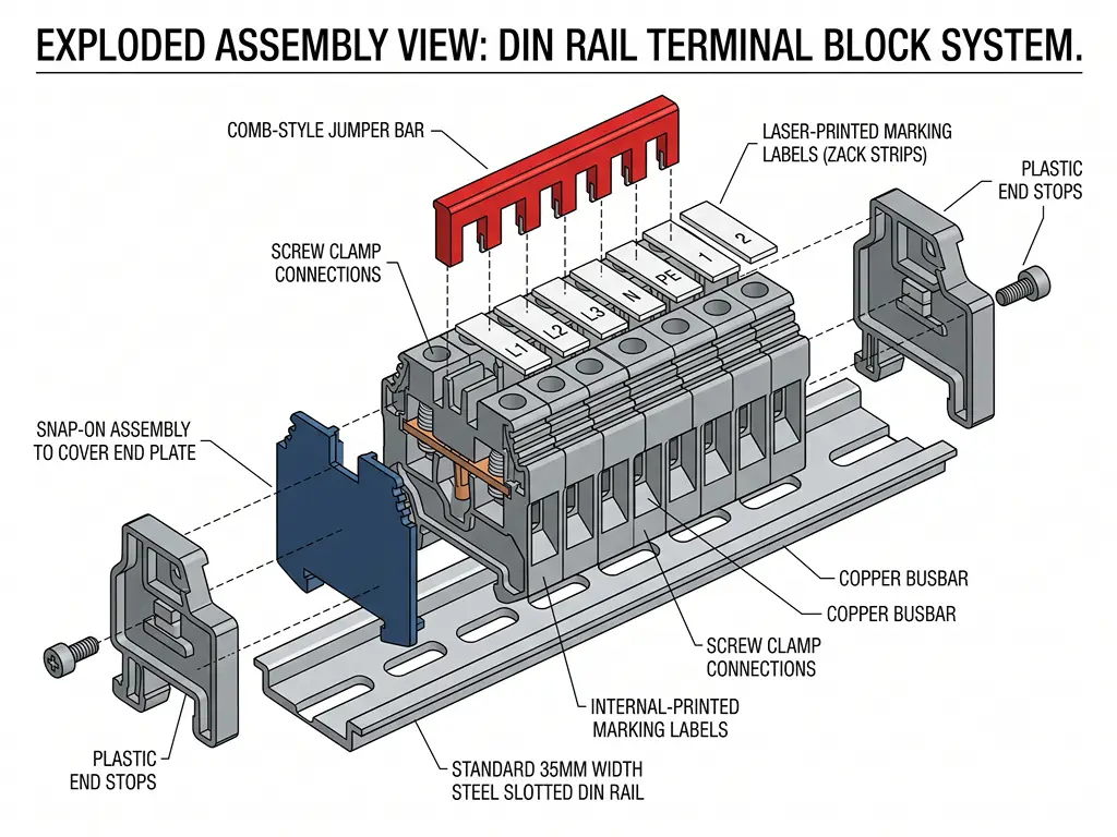
Blok terminal tidak berfungsi secara terpisah. Empat aksesori mengubah deretan blok individual menjadi satu kesatuan yang utuh, aman, dan mudah dirawat.
Pelat ujung pasang pada sisi-sisi yang terbuka dari blok-blok terluar dalam satu baris. Pelat ini memiliki dua fungsi: mencegah jari secara tidak sengaja menyentuh bagian logam yang bertegangan, serta mencegah debu dan kotoran masuk ke sisi-sisi terbuka pada rumah terminal. Baris terminal tanpa pelat ujung merupakan celah keamanan listrik yang berpotensi menimbulkan bahaya.
Penahan ujung (jangkar) Kunci seluruh baris blok pada rel DIN agar tetap pada posisinya. Blok-blok ini berbeda dengan pelat ujung — pelat ujung berfungsi menghalangi aliran listrik, sedangkan penghenti berfungsi menghalangi pergerakan. Kencangkan sekrup penghenti ujung pada kedua ujung baris tersebut hingga menempel erat pada rel, sehingga rakitan tidak akan bergeser meskipun terkena getaran.
Jumper (batang penghubung) Pasang ke bagian atas atau samping terminal yang berdekatan untuk menghubungkannya secara listrik dalam kelompok. Komponen ini menghilangkan kebutuhan akan pemasangan kabel berantai (daisy-chain) dan tersedia dalam dua jenis: sisir kaku yang menghubungkan sejumlah kutub tetap (biasanya 2, 3, 5, atau 10), serta versi fleksibel yang dapat dipotong sesuai panjang yang dibutuhkan. Satu hal yang perlu diperhatikan: nilai arus jumper harus sesuai dengan nilai arus tertinggi dari terminal dalam kelompok yang dihubungkan. Jumper 17,5 A yang dipasang pada terminal 32 A akan menjadi titik terlemah.
Label penanda dan wadah Inilah yang membedakan panel yang dapat diperbaiki oleh teknisi dalam lima menit dengan panel yang membutuhkan waktu dua jam. Strip penanda yang dicetak dengan laser tahan terhadap minyak, pelarut, dan suhu mulai dari -40°C hingga +100°C. Jangan mengandalkan label tulisan tangan — label tersebut akan memudar, luntur, dan memberikan kesan kurang profesional kepada pelanggan akhir Anda.
Bagi distributor dan grosir, margin keuntungan tidak hanya terletak pada blok terminal — melainkan pada posisi Anda sebagai satu-satunya pemasok yang tidak perlu dicari lagi oleh pelanggan Anda. Ketika seorang pembuat panel mendatangi Anda untuk membeli terminal feed-through dan Anda juga dapat menyediakan catu daya rel DIN, relai, sensor, serta pemutus arus yang dipasang di kabinet yang sama, Anda berhasil meraih seluruh kebutuhan pelanggan tersebut. OMCH mengirimkan lebih dari 3.000 SKU di 30 kategori otomatisasi dari satu pabrik di Zhejiang, dengan sertifikasi CE, CCC, dan RoHS, 70 mitra distributor yang sudah beroperasi di lebih dari 100 negara, serta harga langsung dari pabrik yang memberikan ruang bagi margin Anda. Telusuri katalog lengkap di omch.com atau hubungi kami untuk mendiskusikan pengaturan persediaan.
Sediakan rangkaian lengkap komponen otomatisasi untuk pelanggan Anda — semuanya dari satu pabrik.
Lebih dari 3.000 SKU di 30 kategori. Harga langsung dari pabrik. Bersertifikat CE, CCC, dan RoHS.
Daftar Pustaka
- IEC. “IEC 60947-7-1:2025 — Peralatan sakelar dan pengatur tegangan rendah, Bagian 7-1: Peralatan tambahan — Blok terminal untuk konduktor tembaga.” 2025. https://webstore.iec.ch/en/publication/72949
- Onesto Electric. “9 Jenis Terminal Blok Rel DIN yang Umum dan Kegunaannya.” 2025. https://www.onesto-ep.com/blog/9-common-din-rail-terminal-block-types-and-their-uses/
- Premier Cable. “Terminal Sekrup vs Pegas vs Push-in: Mana yang Harus Dipilih untuk Kabinet Industri.” 2025. https://www.premier-cables.com/info/screw-vs-spring-vs-push-in-terminal-103526331.html
- Same Sky. “Panduan Lengkap dalam Memilih Terminal Block.” 2025. https://www.sameskydevices.com/blog/ultimate-guide-to-terminal-block-selection
- Altech Corporation. “Terminal Push-In versus Jenis Sambungan Lainnya.” Electronic Design. https://www.electronicdesign.com/…/altech-corporation-push-in-terminals-versus-other-types-of-connections
- Komunitas PLCtalk.net. “OT: Blok Terminal Rel DIN.” Diskusi forum. https://www.plctalk.net/forums/threads/ot-din-rail-terminal-blocks.74568/
- OMCH. “Konektor & Terminal.” https://www.omch.com/connectors-terminals/
- OMCH. “Halaman Utama.” https://www.omch.com/



 English
  Arabic
  Turkish
  Russian
  Spanish
  French
  Indonesian
  Portuguese
  Thai
Thai  Vietnamese