


One of the most important, but at the same time relatively unknown components in the complicated electrical system of either a modern car or a big machine is the new relay. It also exists in so many systems, like in the fuel as a pump in a car and as a control panel in a factory. When a relay is broken, it may present itself as a drastic, confusing, and seemingly significant problem, a car that will not run, lights that will not work, or machines that remain unused. What is often wrong is a little cheap part which has exceeded its service life but is overlooked. This is a one stop article that will debunk how to diagnose a new relay. We are going to give the stepwise, no-nonsense procedure on how to test any common relay with the assurance and accuracy of the professional technician.
Understanding a Relay’s Role and Failure Points
A relay basically is an electromechanical switch. Its operation can be described as nothing more than clever since it involves the regulation of a very small flow of electrical current to regulate a relatively large flow of electrical current. Consider it as a switch of the remote control. The low-power signal initiates in a computer or a single dash switch that activates a little electromagnet inside of the relay. That magnetic field can then simply draw a piece of metal, an armature, which closes a high-capacity switch and permits high current to flow to a big load such as a starter motor, a cooling fan, or a bank of lights. This puts the sensitive control electronics away from the high-amperage “load” circuit thereby protecting it against voltage surges and overheating.
Despite their robust design, relays are subject to wear and eventual failure. Understanding the common failure points is the first step in effective diagnosis.
- Coil Burnout: Fine wire is used in the manufacturing of electromagnet coil which is located internally. This wire can be broken or shorted out due to over-voltage condition or due to some simple manufacturing fault, which makes the coil inactive to try and create the magnetic field required to energise the switch.
- Contact Pitting or Welding: During each cycle of switch on and off the relay maintains a small electrical arc between contacts. The contact material can be burnt off in this arc after a few thousand cycles due to high current density making them prone to form pits and high-resistance surface that slows down current flow. More rarely, a very large surge current (e.g. due to a shorted motor) may even melt the contacts, permanently welding them together in an open state or in a closed state depending on the instantaneous contacts, contacts open when a closed state was being sought or vice versa.
- Contact Oxidation/Corrosion: Contacts that are made of metal surfaces are prone to oxidize and corrode in a humid or rough environment. This is a thin film of corrosion that provides an insulating layer that blocks current passing even in the event that mechanical contacts between the relay are in place.
- Internal Mechanical Failure: The relay has parts that move. The armature pivot may wear and the switch may not open or close. The return spring may break, so that the switch may not write or leave.
Essential Tools and Safety First
Proper diagnosis would involve the adequate equipment and a certain sense of commitment to safety. It is possible to damage the vehicle, or even injure self attempting to test electrical components in the wrong way. Tools which are essential are simple to use and ready to employ.
| Tool | Description |
| Digital Multimeter | The main diagnostic instrument. The resistance (Ohms) and continuity tests must be carried out to check internal conditions inside the relay coil and contacts. |
| Jumper Wires | Pairs of alligator-clip wire, at least, to safely connect power of an external source to the relay coil to activate it to test. |
| Power Source | A 9V battery is the perfect component to safely power the majority of 12V automotive relays in a work bench. An extreme caution can also be applied with a fully charged car battery. |
| Relay Puller Pliers | A tool which is not necessary, but strongly advisable. It enables you to hold and pull off relays out of fuse boxes without defecting their plastic casing. |
WARNING: SAFETY PROTOCOL
Do not work with any of the electrical parts of a car or pull out the relays in a vehicle without first disconnecting the negative terminal of the car battery. This avoids short circuiting, which may be caused accidentally and makes the sensitive electronics, like the Engine Control Unit (ECU), break or ignite a fire.
The 1-Minute Swap: Your Quickest Test
The swap test is the most effective diagnostic you can make before reaching to a multimeter. This is an approach to testing a circuit, using something that it is known to work as a positive control of the circuit. It is outstanding and does not involve the use of any tools, but the hands or relay puller.
The principle is simple: in almost every vehicle fuse box, there will be several identical relays, each of which is connected to a different circuit. As an example, the horn relay can be the same one as that of air conditioning clutch or fuel pump.
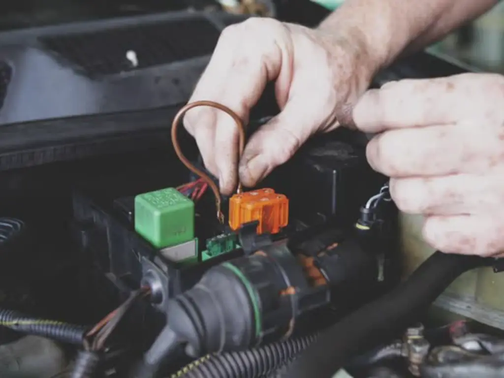
- Locate the Suspect Relay: In order to determine where the suspect relay is look in your vehicle owner instruction book or locate the wiring diagram on the inside of the fuse box lid.
- Identify an Identical Relay: There should be another relay in the same fuse box which has the same part number and pin. Select one off a circuit that is not critical but can be easily tested such as the horn.
- Perform the Swap: Allegedly take out the suspect relay with care. Next, take the known-good relay and take it out of the circuit of the horn and insert them into the socket of the test relay. Insert the suspect relay in the socket of the horn.
- Test the Circuits: Try to energize the circuit that had initially failed. Providing that it is now working you have conclusively shown that the original relay was bad. Use the horn as a last confirmation. When it does not work now you are doubly sure.
This test would be a short cut and isolate the fault to the relay itself and save a lot of time of diagnosis. When the initial problem remains unsolved using known-good relay, then known-good relay is not the source of the problem; the problem is in some other part of the circuit wiring, fuse or control switch.
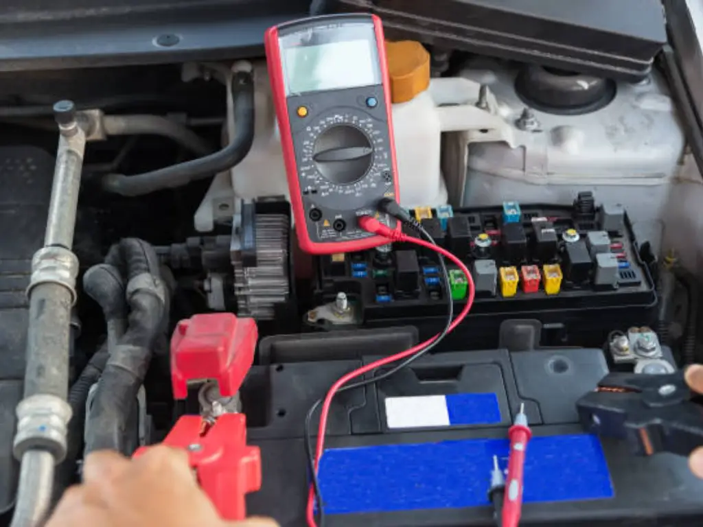
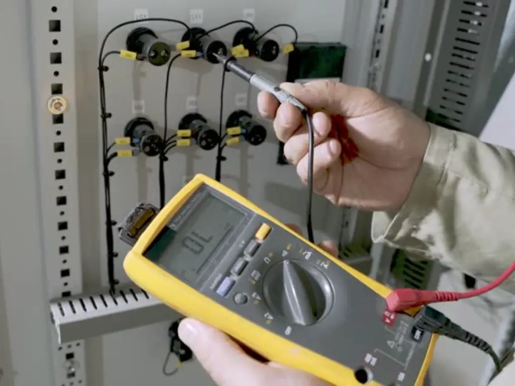
Step-by-Step: Bench Testing with a Multimeter
In case a swap test cannot be carried out or when you want absolute guarantee that something is wrong with a relay, then it has to be tested by a digital multimeter on a workbench. The procedure of checking this takes place with reference to two main internal circuits, one being the control circuit (coil) and the other being the power circuit (contact).
Reading the Pins
The majority of automobiles use a standard set of numberings on their automotive relays, referred to as the Bosch pinout which is generally printed non removably on the relay, on the case itself. It is very important to understand this.
- Pin 85 & Pin 86: Using power ground will apply supply to these two pins and energise the electromagnet. Most normal relays do not care about polarity but a few have protection built in by an internal diode and will be marked; on these, 86 will be positive and 85 negative.
- Pin 30: It is the common contact. The high-amperage power circuit receives it as its input.
- Pin 87: It is the Normally Open (NO) contact. When it is off, Pin 30 and Pin 87 are not connected. With coil energized, the switch is closed and Pin 30 becomes connected to Pin 87.
- Pin 87a: It is the Normally Closed (NC) contact, which is on 5-pin relays only. At rest Pin 30 goes to Pin 87a. This connection is broken when the coil is energized.
Test 1: Checking the Control Circuit (Coil)
The test helps find out whether the internal electromagnet is electrically good.
- Turn your digital multimeter into the resistance reading mode which is usually indicated by a symbol (Ohm) Omega (W). Use the 200 or 2k range.
- Connect the first multimeter probe to Pin 85 whereas the second multimeter probe to Pin 86.
- Notice the reading. The reading on a healthy relay coil should have a resistance relatively between 50 and 120 Ohms within a 12V relay coil.
- Interpreting the Result:
- On dialing inside this range, the coil is okay.
- When a meter is set to OL (Open Loop) or read an infinite resistance, the internal wire of the coil is broken. The relay is poor.
- When the meter display shows that the resistance is very low (close to 0 Ohms), the coil is short-circuited. The relay is poor.
Test 2: Checking the Power Circuit (Contacts)
This test tests the high-power switch contacts in default mode.
- Turn your multimeter to the continuity mode. This can be denoted by a diode/sound wave. In this mode, the meter will sound in case it knows that it has a complete circuit (lowest resistance).
- For a 5-pin relay: The probes are touched between Pin 30 and Pin 87a. The meter ought to beep pointing out that the connection, which is normally open is intact.
- For all relays: Put the probes in contact with Pin 30 and Pin 87. The meter ought to be silent, thus showing that the normally open connection is actually open.
Should one of such tests prove unsatisfactory, e.g. you obtain continuity between 30 and 87 at rest, the contacts of the relay are shorted or welded internally. The relay is bad.
Activating the Relay for a Live Test
A relay that passes the static bench checks has to be tested on power. The final test is assuring the electromagnet is sufficiently strong not just to move the switch physically but also that the switch contacts are capable of carrying a current.
- Make ready your source of power. The safest practice proposed is by the 9V battery. Connect the jumper wires on the battery terminals.
- Apply the power to coil. Connect the end of a positive jumper wire to Pin 86 and then the end of the negative jumper wire to Pin 85.
- Watch and listen to the Click. As soon as you make the connection, try and listen to a clicked sound that should be pronounced as a sharp click. That is the snapping of the internal armature. Take a firm click, a very weak click or a buzzing sound, there is a mechanical failure of the relay.
- Exercise the contacts under power. Repeat the continuity experiment of the last with power still applied to pins 85 and 86.
- Touch the two multimeter probes at Pin 30 and Pin 87. The meter should now beep when on high to indicate that the normally open circuit should now be closed properly.
- In case you are having a 5-pin relay, you should connect the probes to Pin 30 and 87a. The meter is now supposed to quiet down, which is a confirmation of the normally closed circuit opening properly.
If the relay clicks and passes these live continuity tests, it is fully functional.
Interpreting Results and Finding a Quality Replacement

The series of tests provides a complete diagnostic picture. Use this table to make a final determination.
| Test Step | Expected Result | Faulty Result | Diagnosis |
| Coil Resistance | 50-120 Ohms | OL (Infinite) or ~0 Ohms | Bad Coil |
| NC Contact (Rest) | Continuity (Beep) | No Continuity | Bad NC Contact |
| NO Contact (Rest) | No Continuity | Continuity (Beep) | Welded Contacts |
| Activation | Sharp “Click” | No Click / Buzz | Mechanical Failure |
| NO Contact (Active) | Continuity (Beep) | No Continuity | Bad NO Contact |
| NC Contact (Active) | No Continuity | Continuity (Beep) | Welded Contacts |
Once your tests indicate that the relay is faulty, then you have to find a good replacement. Although the typical auto parts store relays are functional, in high-demand applications or just to sleep well at night, it is a good idea to use an industrial-grade component.
We produce high quality stuff at OMCH, our relays are made according to stricter standards than the consumer parts. Our products are durable and they perform in the same way without you getting to do this job twice. Good relay is not a component.
Troubleshooting: What if the Relay Isn’t the Problem?
The comedy in this matter is that a relay will pass all the tests but the circuit fails to fail again; frustrating but expectable. This shows that the relay itself is okay and the problem is there. Then your interest should be changed towards the circuit. Here in this case a systematic approach would be priceless.
- Check the Fuse: A fuse is virtually always applied to a relay. Take out the matching fuse and test with your multimeter to see continuity. Do not use only the visual examination since hairline cracks can be unseen.
- Check the Relay Socket: It may be the power and signals to the relay. Test the pin sockets in the fuse box by your multimeter (DC Volts mode, with the key on). The socket of Pin 30 (main power) and Pin 86 ( control power ) should read 12v. At the socket, you ought to locate a good ground (near 0V) against Pin 85. In case of any of these missing, then you have a wiring problem.
- Check the Control Switch: The signal that ins the pin 86 is provided by a switch (e.g., button on your steering wheel, a toggle on a dash, a sensor). You need to verify whether that switch is working or not by putting it in continuity when closed.
- Inspect the Wiring: Trouble shoot the connections going in and out of the relay socket. Examine wires and cables and inspect them to find obvious damage, i.e. chafed insulation or green corrosion in connectors or loose ground connections. One of the bugs is a bad ground connection, probably the most difficult to find and a very common electrical nuisance.
Relay Testing FAQ and Key Takeaways
Q: What is the way to test a relay?
A: The quickest method is with a known-good relay, the so-called “swap test”. A bench test using a multimeter is the most conclusive: measure the resistance with the multimeter (should be pre-selected to match the coils resistance range of 50-120 ). Put connections on the correct pins (test the connections on the correct pins with the multimeter in continuity mode, the multimeter should make a beep) and then apply voltage to the coil to see whether or not it makes a click and opens or closes the contacts that changes the continuity state between the contacts.
Q How can I test a 4 pin relay using a multimeter?
A: A 4-pin relay has 85, 86, 30 and 87 pins. First, check the coil by testing resistance of 85-86. Second, make sure there is a lack of continuity between 30 and 87. 3rd, put 12V between pins 85, and 86; the relay should click, and you will now have continuity between 30, and 87.
Q How much resistance is supposed to be on a 12V relay?
A: A normal 12- volt automotive relay will have a coil resistance of 50 to 120 Ohms. Very low or infinite (OL) reading would be an indication of a defective coil.
Q: What is the way of troubleshooting a starter relay?
A: A starter relay which is usually termed as solenoid is just a very high-powered relay. The principles of tests are the same. It is possible to check resistance in the low-amperage control circuit (can be two small terminals). Then high-amperage posts (two large studs) can be tested against absence of continuity. Ensure that when you energise the control terminals with 12V the solenoid clunks very loudly, and then you should find that the two large studs are now continuous. This is usually applied on the vehicle.
Key Takeaways
- Always prioritize safety by disconnecting the battery before working on electrical circuits.
- The “swap test” is the quickest method to diagnose a faulty relay.
- A multimeter is essential for definitively confirming a relay’s condition by testing its coil resistance and contact continuity.
- A complete test involves checking the relay both at rest (static test) and when activated with power (live test).
- If a relay tests good, the fault lies elsewhere in the circuit, requiring you to check fuses, wiring, and power/ground at the relay socket.


