


Understanding the “Industrial” Context: It’s Not Just About Continuity
Industrial Limit Switches act as the silent guardians of the production process in the world of Industrial Automation. While the switch itself is a simple ON/OFF device used to detect presence, position, or limits, the high-stakes environment dictates how it must be tested. A robotic work cell failure is not merely a question of irritation; in highly Automated Systems such as automotive or packaging lines, it becomes a question of significant revenue loss. In these sectors, the downtime cost can easily escalate to hundreds or thousands of dollars per minute.
To understand the testing procedure, one must understand the ecosystem. A limit switch operates within an Industrial Control System (ICS). Unlike a home automation switch that merely breaks current flow, a switch in an ICS does not directly drive a motor. Rather, it is a logic input that transmits a 24 V DC (or 110 V AC) control signal to industrial computers, PLCs, or controllers used in CNC machining. The signal is processed by the controller to execute internal logic and make a critical decision.
This is a vital distinction. A switch that appears to be operating “a-okay” on a simple continuity beeper may still fail to drive a PLC input high due to contact resistance or signal noise. Furthermore, unlike microwave door switches, components mounted on industrial equipment are subjected to harsh environments, including electromagnetic interference (EMI), coolant mist, and the mechanical vibration inherent to machine operation.
If the advice you seek is for repairing a microwave or domestic appliance, the test steps outlined below will be unnecessarily complicated and potentially hazardous. The following resources are far more suited to domestic repairs:
| Resource Type | Recommended Search / Source | Best For |
| Video Tutorial | YouTube: “How to Test Microwave Door Switch” Watch Video | Home appliance repair (Microwaves) |
| Blog Guide | Sun Heating: “How to Test Furnace Limit Switch Quickly and Easily” Read Guide | Residential Heating (HVAC) systems |
| Blog Guide | AppliancePartsPros: “How to Test a Furnace Limit Switch with a Multimeter” Read Guide | Detailed multimeter testing procedures |
However, a well-structured and comprehensive testing plan is required for professionals responsible for the uptime of palletizers, VMCs, conveyor systems, or injection molders. The goal is not merely to verify that the switch works on a test bench, but to ensure it functions correctly within the entire control loop of your automation systems.
Preparation: Safety Measures and Tools
There must be some degree of accuracy when you troubleshoot automation failures. It is strongly recommended not to depend on calculations, or even so-called “wiggling wires” on a conductor which may be part of the problem. This practice risks causing physical damage to delicate connectors and will surely cause many intermittent faults that will accompany you and plague your shift the whole time you are there. Take some time to ensure you have the necessary instrumentation and that you have established a safe working perimeter before going to the machine.
The Toolkit
To be able to test industrial control circuits successfully and reliably, you will require more than a mere continuity tester.
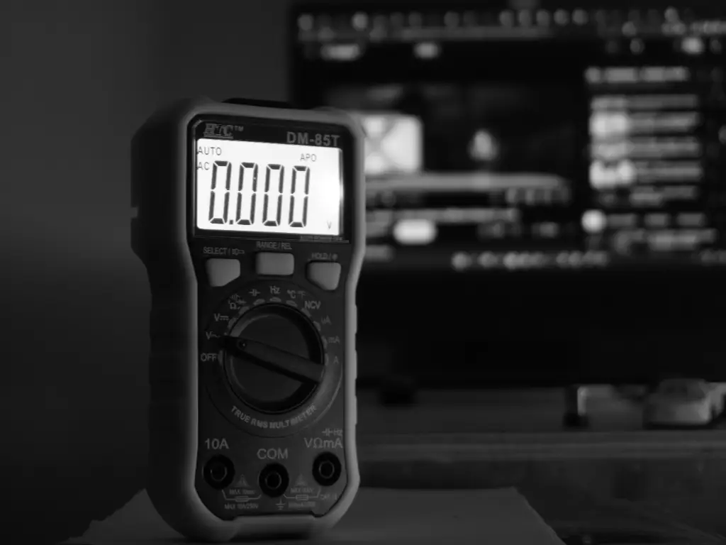
- True RMS Digital Multimeter: The reason why you need to be using a Fluke or Hioki brand device is as important as the accuracy of the device in measuring DC voltage. A high impedance is required to prevent circuit loading, although a low impedance (LoZ) mode can be helpful in some ghost voltage cases.
- Alligator Clip Leads: You can never have probes in your hand and operate a machine manually. To make it easier to use, alligator clips that screw or push on are of good quality to be used in hands-free monitoring of voltage drop as the machine is cycled.
- Terminal Screwdrivers: To install screw panels, a small set of insulated screwdrivers is required, the most common size required is the flathead 2.5mm and 3mm.
- Jumper Wire (with fused protection): These are wires that are handy in temporarily bypassing a switch to test PLC logic. Nevertheless, great care should be exercised.
Safety First (LOTO Standard)
In the majority of cases, work will have to be done on live circuits (24V DC voltage) due to the nature of the testing that will be required. The machine, however, should be isolated under strict safety procedures as stipulated in standard PPE / LOTO protocols.
Lockout/Tagout (LOTO): In the case of physical switch enacted hand inspections, machine motive power (pneumatic, hydraulic and electrical motor power) should be isolated and locked out. Any gravity fed loads should be properly secured.
Live Testing Protocol: To perform electrical testing: in case you require control power to be restored:
- Clear all personnel from the cell.
- Wear appropriate PPE (voltage-rated gloves and eye protection), even for 24V control systems, to protect against arc flash from a shorted high-current power supply.
- Only a de-energized circuit should be tested in terms of resistance to Ohms. Conversely, voltage testing is performed on a live circuit. Confusion of these two will melt the fuses of your meter, and may also destroy input cards on the PLC.
Step 1: Preliminary Diagnosis via PLC/CNC Interface
The finest troubleshooters will not remove the toolbox at once, but will examine the control system. One of the most valuable and the best resources that will provide you with a preliminary diagnostic is the brain of the machine—typically a Programmable logic controller (PLC) or a Computer numerical control (CNC) unit.
Interpreting Input LEDs on Your PLC Controller Module
Locate the input card on which the limit switch is attached. In the realm of PLC automation, status LEDs are provided on all channels for input devices on most industrial PLCs (Siemens, Allen-Bradley, Mitsubishi, Omron). To truly understand the PLC meaning of a fault, you must compare the physical state of the switch to the logic state on the module.
- Actuate the Switch: Manually trigger the limit switch (if safe) or observe the machine state.
- Scenario A: The LED lights up, yet the device acts as though the switch is open. The test conclusions must show that the switch and the field wiring are likely to be fine. The problem lies in the program logic—a forced value in the software, or a burnt out internal opto-coupler on the input card of the PLC systems.
- Scenario B: When the switch is switched on, the LED does not turn on. The conclusions of the test prove that the signal is not reaching the process control processor. The issue lies in the field: the problem is the switch, the cable, the terminal block, or the distribution of 24V power supply.
Checking CNC Homing Errors and Alarm Codes
Limit switches are used in CNC applications to execute specific control functions, serving as the boundary between physical movement and digital safety for Homing (Reference) and Overtravel (Hard Limit). Unlike output devices which receive commands, these switches provide critical feedback.
- “Hard Limit Reached” / “E-Stop” Alarm: Industrial safety circuits usually wire overtravel switches in “Normally Closed” (NC) series loops. If a wire breaks or a switch fails, the machine interprets it as hitting the end of the axis. If the machine is in the center of its travel but reports a hard limit, the test indicates a broken circuit (open loop).
- “Homing Failed” / “Reference Return Incomplete”: This usually indicates the deceleration dog was hit, but the zero-point signal (often from the same switch or an encoder pulse) was not received within the expected time window. This points to a sticky switch actuator that didn’t release quickly enough, or a dirty sensor face.
| LED Status | Physical Switch State | Diagnosis Location | Likely Cause |
| OFF | Open (Not Pressed) | Normal | System Standing by. |
| ON | Closed (Pressed) | Normal | Signal loop is healthy. |
| OFF | Closed (Pressed) | Field / Wiring | Broken wire, failed switch, or 24V supply loss. |
| ON | Open (Not Pressed) | PLC / Logic | Forced “True” in software, shorted cable, or welded contacts. |
| Flickering | Closed (Pressed) | Switch Contacts | High contact resistance (corrosion) or loose terminal. |
Step 2: Visual and Mechanical Inspection (The “On-Machine” Check)
Test the mechanics before testing the electronics. The mechanics in such places are very rough. A limit switch is a mechanical device, including a moving target. When inspecting limit switches, visual defects such as physical damage or misalignment are often the most prevalent cause of a testing failure.
- Actuator Integrity: Test the actuator / roller components, specifically the lever, plunger, or the whisker. Is it bent? Is the roller not moving? A roller that is not in motion serves as a brake and generates friction and ultimately leads to mechanical failure where it breaks the lever arm.
- Cam/Dog Condition: Check the cam on the machine which is to strike the switch. Is it worn? Has it shifted to another place? When the switch is not pressed by the cam to the extent of reaching positive opening then the electrical contacts will not change. Should it press the switch to the extent of reaching that positive opening, then it would be excessive and the internal mechanism would be ruined.
- Cable Strain: First check the stress points. Pull conduit or cable must be fine. Stress points that are high should not have been relocated. The screw terminals are not the only ones that are connected to internal wires. They can be attached to the switch housing.
Step 3: Electrical Testing Procedures (Multimeter Guide)
In case all the above tests are passed, we have to perform some electrical integrity tests. This is what junior technicians often fail to do, leading to frustration. Accurate testing is essential to maintain precise control over signal levels and ensure the integrity of automated control at the I/O level.
Testing Mechanical Switches: Voltage Drop vs. Resistance
The trap of the beep test. Over-dependence and failure to pass the continuity test (beep) or the Ohms test is poor practice. The reason is that most multimeters can only measure small voltages (3 or 9 volts) and have a relatively low measuring circuit (low current used). It could be that a contact on a limit switch has developed copper-oxide (or some other insulating) on it that the multimeter will not be able to punch through (but it may actually measure Open, or vice versa: indicate Closed (0 Ohms). This would mean that contact is low-Ohmic, or you may be experiencing a case where large under-load switch is present, which has actually very large resistance, balanced with a small amount of low-current bypass.
The Solution: Voltage Drop Testing (Live Circuit)
- Keep the machine powered (24V control power only).
- Place your black probe on the 24V Common (0V) at the terminal block.
- Place your red probe on the InputTerminal of the PLC connected to the switch.
- Switch Open: You should measure 0V (or a floating low voltage).
- Switch Closed: You should measure nearly the full 24V.
- Critical Analysis: If you measure 18V or 19V instead of 24V, the PLC input LED might flicker or stay off. This indicates High Contact Resistance. The switch is mechanically closing, but the internal contacts are corroded or pitted. The switch must be replaced.
Testing Inductive & Photoelectric Sensors (NPN vs. PNP)
Solid state sensors (proximity switches) do not contain dry contacts; therefore, they do not utilize ohmmeters. You should be in a position to distinguish between the NPN/PNP configurations—specifically systems with PNP (sourcing) logic versus those with NPN (sinking) logic. Understanding NPN vs PNP wiring is critical for correct diagnosis.
- Standard Industrial Wiring (DC 3-Wire):
- Brown: +24V DC
- Blue: 0V DC
- Black: Signal (Load)
- Testing a PNP Sensor (Common in Europe/USA):
- Red Probe on Black (Signal) wire.
- Black Probe on Blue (0V) wire.
- Target Present: Meter reads +24V.
- Target Absent: Meter reads 0V.
- Testing an NPN Sensor (Common in Asia):
- Red Probe on Brown (+24V) wire.
- Black Probe on Black (Signal) wire.
- Target Present: Meter reads +24V.
- Target Absent: Meter reads 0V.
- Troubleshooting Tip: If the sensor LED lights up but you get no voltage change on the signal wire, the output transistor inside the sensor is likely shorted or “blown open” due to a previous overload.
| Sensor Type | Red Probe Location | Black Probe Location | Target ABSENT | Target PRESENT |
| Mech. Switch (Dry Contact) | PLC Input | 0V / Common | 0 V | 24 V DC |
| PNP Sensor (Sourcing) | Black Wire (Signal) | Blue Wire (0V) | 0 V | 24 V DC |
| NPN Sensor (Sinking) | Brown Wire (+24V) | Black Wire (Signal) | 0 V | 24 V DC |
Advanced Diagnosis: What if the Switch Tests “Good” but Fails Under Load?
The bane of industrial maintenance is intermittent malfunctions, including “ghost faults.” The machine halts repeatedly, but the switch functions perfectly when tested statically. These issues are seldom stagnant; they lean towards dynamic failures that only appear during actual machine function. These are often exacerbated by harsh environments involving vibration, EMI, or extreme temperatures that affect electronic stability under tight temperature control conditions.
Cable Fatigue in Drag Chains: The cables in robotics or gantry CNCs will bend millions of times. The insulation may not be broken and the copper strands may be broken. The connections appear fine when the machine is in a standstill (home position), but when the axis moves to a certain position, the cable bends, copper strands rupture and the signal is lost.
- Test: Wiggle the cable vigorously along its entire length while monitoring the continuity or voltage.
Vibration & Contact Bounce: If a machine vibrates heavily (e.g., a punch press), a standard snap-action switch might experience “contact bounce.” The contacts physically separate for microseconds. A modern, fast-scanning PLC might read this micro-break as a stop signal.
- Remedy: Check PLC input filters (increase the debounce time in software) or switch to a sensor with no moving parts (inductive).
EMI/Noise: If the limit switch cable runs parallel to a VFD motor cable in the same wire duct, the high-frequency noise can induce a “phantom” voltage on the limit switch line. The PLC sees 24V when it should be 0V.
- Test: Measure AC voltage on the DC signal line. Anything over a few volts AC indicates induction. Use shielded twisted pair cables to resolve this.
Why Do Industrial Limit Switches Fail?
In fact, in order to discuss prevention, we must discuss the pathology of mechanical failure. What is it that causes components to die?
- Liquid Ingress (The #1 Killer): Cutting and washdown fluids are frequently detergents that have low surface tension molecules. This allows coolant ingress to occur, creeping around suboptimal rubber seals easily. When liquid ingress takes place, the contact grease is mixed with the fluids to form a conductive mess or an insulating, non-conductive, gunky fluid.

- Mechanical Overload: The switch body is used as a mechanical stop. The switch is not supposed to be the physical limit barrier of the system when using a 2-ton gantry system. This misuse leads to severe physical damage.
- Wrong Material Selection: Using a generic plastic-bodied switch in a welding cell (sparks melt the housing) or a food processing line (caustic cleaners crack the ABS plastic). These standard switches cannot survive extreme temperatures or the chemical attacks typical of harsh environments.
This leads to the most significant discovery, which is that no amount of testing in the world will assist when the component is not fit in the first place.
Prevention Strategy: Choosing the Right Switch for Harsh Environments
Reliability engineering dictates that the best way to fix a recurrent fault is to design it out. If you find yourself replacing the same limit switch on a specific axis every three months, you do not have a maintenance problem; you have a specification problem. The permanent remedy is to stop replacing “like for like” and instead upgrade to components engineered to withstand the specific stressors of your facility.
Strategic Specification: Matching the Component to the Stressor
Before purchasing a replacement, analyze the “kill factor” of the previous failure. Was it physical impact? Liquid intrusion? Or electrical contact burnout? In industrial environments, a generic switch often fails because it cannot handle the specific intersection of mechanical and environmental stress.
When selecting a limit switch for automated machinery, use the following matrix to ensure the specification matches the application reality:
| Failure Symptom | Root Cause | Required Specification Upgrade |
| Housing Cracked / Lever Snapped | Excessive impact or “over-travel” by the machine cam. | Metal Actuator Head: Choose die-cast aluminum heads (IK06+) over plastic. |
| Internal Corrosion / Sludge | Coolant or washdown fluid enters the seal. | IP Rating: Upgrade to IP65 or IP67. Ensure cable glands are tightened to torque specs. |
| Sluggish Return / Stickiness | Temperature extremes thicken the grease. | Wide Temp Range: Verify spec covers -20°C to +70°C (Standard Industrial) without derating. |
| Contact Welded / Burned | High inrush current or arcing. | Contact Material: Select Silver Alloy (Ag) contacts; ensure “Double-Break” mechanism for snap action. |
| Signal “Ghosting” / Noise | Vibration causing micro-contact separation. | Snap Action: Avoid “slow break” switches in high-vibration zones; verify >10G vibration resistance. |
The OMCH Advantage: Smart Standardization for ROI
Stop managing mismatched brands. OMCH streamlines procurement with a One-Stop Solution to cover every application. Our Smart Hybrid Construction pairs IP65 die-cast aluminum heads with reinforced plastic bodies, delivering industrial durability against coolants—without the premium price tag. Featuring a -20°C to +70°C range and 10A Double-Break Silver Alloy contacts, OMCH switches can drive resistive loads directly, allowing you to bypass intermediate relays in standard control circuits to optimize your BOM. Standardization means less downtime and higher efficiency.
Ready to upgrade your reliability? Visit https://www.omch.com/ to request our catalog or a free sample for your next project.
Conclusion: Minimizing Downtime Through Proper Maintenance
The logical operation of testing industrial limit switches implies checking the PLC status, followed by a mechanical check, and a check of different voltages. Having the understanding of industrial automation systems—where PLCs act as logic devices in a relatively hostile environment—allows faults to be diagnosed faster and more accurately.
However, diagnostics should be examined further. A proactive maintenance manager does not examine the stack of failed switches and end at the query, “Why?”. Through an active selection of switch components that offer the necessary ingress protection, mechanical life, and temperature resilience, maintenance transforms from constant fire-fighting to scheduled precision, ultimately boosting overall production efficiency.
Ensure that the tool bag contains the necessary meter, the safety measures are not violable and the spare parts crib is well incorporated and well stocked with parts that can fit the industrial gears.


