


The electrical switch is a cornerstone in the advanced environment of the industrial automation and electronic design. Even though mechanical switches are being supplanted by solid-state electronic switches, physical production and disconnection of an electrical circuit through mechanical means offers unparalleled reliability, galvanic isolation, and haptic feedback. This guide delves into the intricate engineering of mechanical switches, taxonomic examination of the numerous categories of electromechanical switches, and a code of conduct on how to choose and optimize them under extreme conditions to electronic equipment.
Fundamentals: How Modern Electromechanical Switches Function
At its most elemental level, an electromechanical switch is a transducer that converts mechanical energy—typically from a human finger or a machine part—into an electrical state change. However, the inner workings of the modern day electronic equipment are not so simple.
The working principle is mechanical contacts. These contacts are forced together with sufficient force to allow the flow of electricity with the minimum of resistance with the switch being Closed. This is a flow of electrons that occurs together in the contact interface. When “Open,” the contacts are physically separated by an insulating medium (usually air), creating an open circuit that prevents current flow.
The Physics of Contact Resistance
Contact Resistance is a natural phenomenon of mechanical contacts. This is the addition of the constriction resistance which is the consequence of the fact that surfaces are microscopically rough and can only be in contact at some a-spots, and film resistance which is caused by oxidation or contaminants. High-quality switches are engineered to provide a “wiping action,” where the contacts slide against each other during actuation to scrub away oxidation, ensuring a low-resistance connection over millions of cycles.
Dielectric Strength and Air Gaps
Dielectric Strength of a switch is also dependent on the distance between open contacts. In high voltage industrial use, this gap should be large enough to avoid “arc-over”. The mechanical housing of the switch is equally critical; it must be constructed from high-performance polymers or ceramics that can withstand thermal stress and prevent leakage currents between terminals.
Core Classifications: Comparing Toggle, Rocker, and Tactile Switches
To select a suitable type of switch, it is necessary to be conversant with the vast taxonomy of mechanical interfaces. Any kind of switches is designed to fit particular ergonomics, space and electrical loads in various applications.
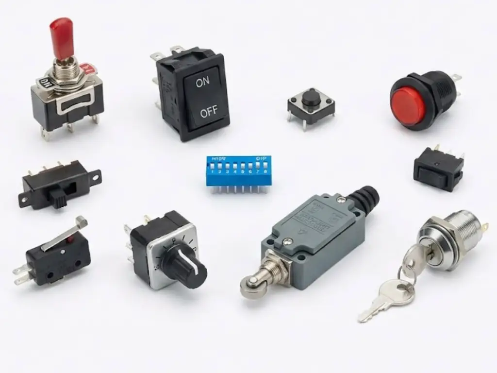
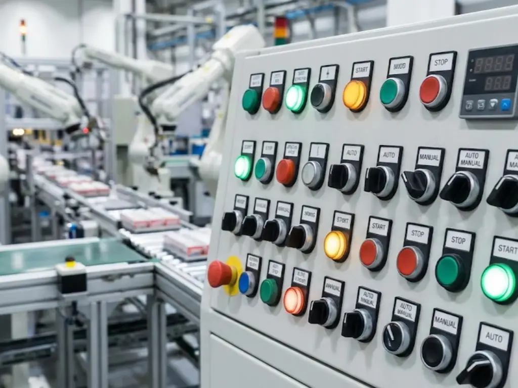
- Toggle Switches: Characterized by a protruding lever (the “bat”), these are the workhorses of industrial control panels. They give convenient visual location of the switch and can be manipulated by gloved hands easily.
- Rocker Switches: These feature a “seesaw” mechanism. They are applied to power distribution units since they are low profile and can be lit. They provide a stable, maintained state.
- Tactile (Tact) Switches: Tactile switches are very small momentary switches that are used in PCB mounting. Their characteristic aspect is the “clicking” or touchy snap, that notifies the user that the circuit is complete.
- Pushbutton Switches: Available in both momentary (spring-back) and maintained (latching) versions. Temporary versions are restored to their initial state as soon as they are discharged. Industrial versions usually have emergency stops (E-Stops) in the form of “mushroom heads”.
- Slide Switches: These utilize a linear sliding motion to open or close contacts. They are perfect in mode selection in small consumer and industrial electronics.
- DIP Switches: A series of tiny switches in a Dual In-line Package. They are used on circuit boards to set semi-permanent configurations or addresses.
- Micro-Switches (Snap-Action): Microswitches use a spring-loaded “over-center” mechanism that causes the contacts to snap between positions at a specific trip point. They are ubiquitous in safety interlocks and limit-sensing.
- Rotary Switches: Rotary switches are switches that are chosen by turning a knob and they contain over two circuit paths. They are required in complicated signal routing or multi-stage equipment control.
- Limit Switches: Rugged switches are operated by machine part motion. They are designed to detect position, end of travel or object presence under harsh factory conditions.
- Keylock Switches: These are used to provide a level of security where the switch state can only be changed with a physical key so that unauthorized people cannot operate important machinery.
Circuit Architectures: Mastering Poles, Throws, and Configurations
Circuit integration requires the internal logic of a switch. This nomenclature is used to describe the number of poles that the switch controls and the number of positions (throws) that the switch can connect to.
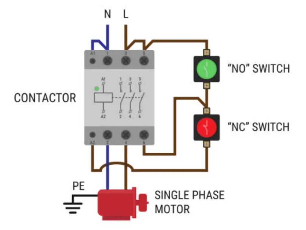
- Pole: Refers to the number of separate circuits the switch controls. A Single Pole (SP) switch is used to operate one circuit; a Double Pole (DP) switch is used to operate two independent circuits at the same time.
- Throw: Refers to the number of output paths each pole can connect to. A Single Throw (ST) is a simple ON/OFF. A Double Throw (DT) connects a common terminal to one of two different paths.
Common Configurations
- SPST (Single Pole, Single Throw): The basic ON/OFF switch.
- SPDT (Single Pole, Double Throw): A “changeover” switch. Useful for toggling between two functions (e.g., Manual vs. Auto mode).
- DPDT (Double Pole, Double Throw): Essentially two SPDT switches operated by a single actuator. Often used for motor reversing or controlling two different voltages with one click.
- NO (Normally Open) vs. NC (Normally Closed): This defines the “resting” state of the switch. An NO switch only completes the circuit when pressed; an NC switch breaks the circuit when pressed.
Industry Standards: Compliance, IP Ratings, and Safety Certifications
In a globalized manufacturing environment, compliance is not optional—it is a prerequisite for safety and market access.
IP (Ingress Protection) Ratings
The IP rating (e.g. IP67) is essential to switches that are exposed to the elements.
- The first digit (0-6): Defines protection against solids (dust).
- The second digit (0-9K): Defines protection against liquids.
- IP67 rating implies that the switch is completely dustproof and can be submerged in water to a depth of 1 meter, which is suitable in the outdoor or wash-down setting.
Safety and Quality Certifications
- UL/CSA: This is necessary in North American markets, and the switch has to be of high fire and electrical safety standards.
- CE: Refers to compliance with health, safety and environmental protection requirements of products sold in the European Economic Area.
- RoHS/REACH: Certifies that the switch does not contain hazardous substances like lead or mercury.
- ISO 9001: A management certification that guarantees that the manufacturer has maintained uniform quality in its processes by standardization.
Selection Criteria: Electrical, Mechanical, and Environmental Factors
Choosing the right electromechanical switch requires a multi-dimensional analysis of various technical parameters. Being one of the leading manufacturers with a history of operation since 1986, OMCH understands that the effectiveness of an automated system is determined by the stability and precision of the smallest elements.
- Electrical Load Requirements
The voltage and current ratings that the switch will be required to handle are the main factors. You must distinguish between Resistive Loads and Inductive Loads. Inductive loads produce large back-EMF, and this may result in severe arcing, especially when dealing with higher voltage systems. OMCH offers more than 3000+ models and specifications, all of which are thoroughly tested to withstand certain electrical stresses, so that no matter what you are switching—a low-signal sensor or a high-power AC line—the component will be stable.
- Mechanical Life and Actuation
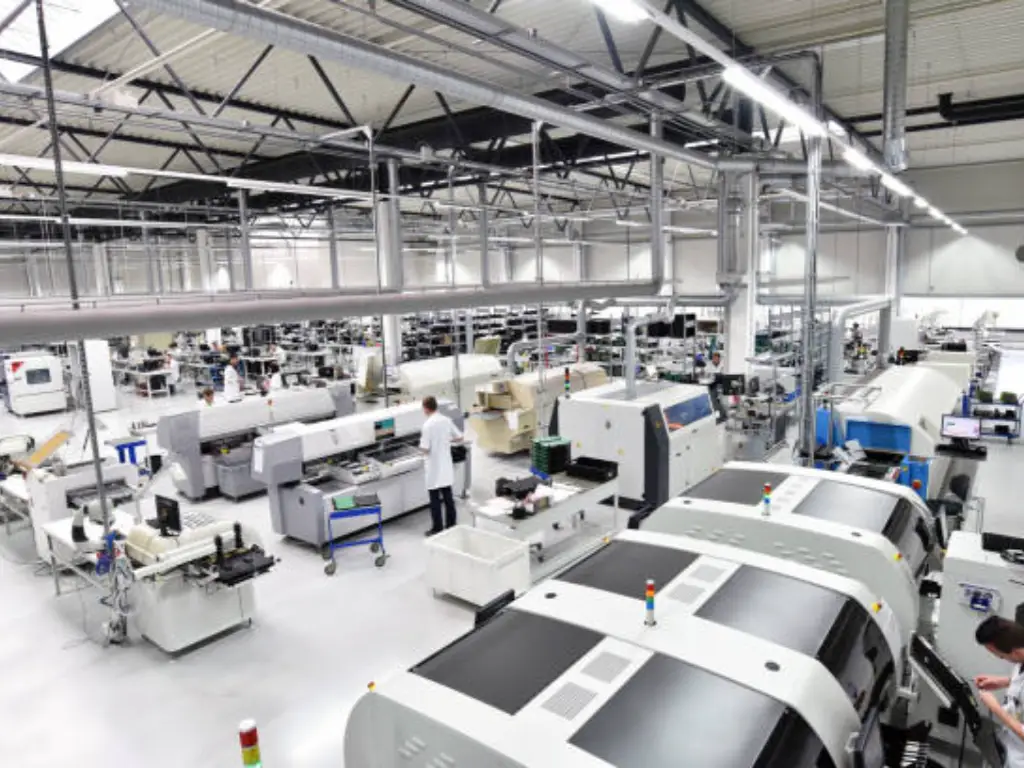
What is the number of times that the switch will be operated? The measure of mechanical life is in cycles. While a consumer switch might be rated for 10,000 cycles, industrial machinery switches from OMCH are engineered for millions of actuations. Our 8,000 sqm modernized plant uses 7 high-level production lines so that the spring tension and contact alignment are precise and the “Tactile Force” and “Travel Distance” remain constant during the life of the product.
- Environmental Resilience
Switches used in heavy industrialequipment are exposed to vibration, high temperatures, and chemicals. OMCH products are made to suit a wide variety of differentapplications, including freezing outdoor depots or high-heat processing plants. Our commitment to quality control—including incoming, in-process, and final inspections—guarantees that our components maintain their integrity under mechanical shock and vibration.
- The “One-Stop” Advantage
In the case of equipment manufacturers, sourcing is concerned with efficiency. OMCH has a one-stop benefit, as it does not only deal with switches but also with power supplies, sensors, and pneumatic parts. We have 24/7 rapid response and technical support, and we are located in more than 100 countries worldwide and 86 branches in China. When you select an OMCH switch, you are leveraging 38 years of R&D and a supply chain that supports over 72,000 customers worldwide. Our products are based on IEC and GB standards, so that your end machine can be exported to any country with all the compliance.
Electromechanical vs. Solid-State: Choosing the Optimal Solution
The Electromechanical Relays/Switches (EMR) vs. Solid-State electronic switches (SSR) is an issue of trade-offs.
| Feature | Electromechanical Switch | Solid-State Switch (SSR) |
| Galvanic Isolation | Physical gap provides total isolation. | Limited to optical/transformer isolation. |
| Contact Resistance | Extremely low (milliohms). | Higher (voltage drop across semi-conductor). |
| Switching Speed | Slow (milliseconds) due to mass. | Fast (microseconds). |
| Lifespan | Finite (mechanical wear). | Virtually infinite (no moving parts). |
| EMI/RFI | Generates noise during arcing. | Minimal noise (Zero-cross switching). |
| Heat Dissipation | Minimal heat generated at contacts. | Requires heatsinks for high currents. |
| Cost | Generally lower for high-power. | Higher for equivalent power ratings. |
For safety-critical applications where a “True Off” state is required (such as emergency stops), the electromechanical switch is superior because it provides a physical air gap that a failed semiconductor cannot guarantee.
Addressing Technical Challenges: Contact Bounce and Arcing Mitigation
To design a high-performance system, it is necessary to take into consideration the nature of flaws of mechanical motion.
Contact Bounce
Mechanical contacts do not remain closed as soon as they are closed. They are elastic and have momentum and thus they “bounce” a few times before stabilizing and returning to a steady state rather than their original position. This may be understood as a series of “on/off” signals in digital circuits.
- Solution: Debouncing has to be applied by engineers. This may be through hardware (an RC filter or a Schmitt Trigger) or through software by adding a delay (usually 5ms to 20ms) before the microcontroller records the input.
Arcing and Contact Erosion
When a switch opens under load, the current tries to keep flowing across the increasing gap, ionizing the air and creating an Arc. This arc produces a lot of heat, which melts and flows through contact material.
- Arc Suppression: For DC loads, a Flyback Diode is placed across the inductive load. For AC loads, an RC Snubber (resistor and capacitor in series) is placed across the switch contacts to absorb the energy of the spark, significantly extending the life of the switch.
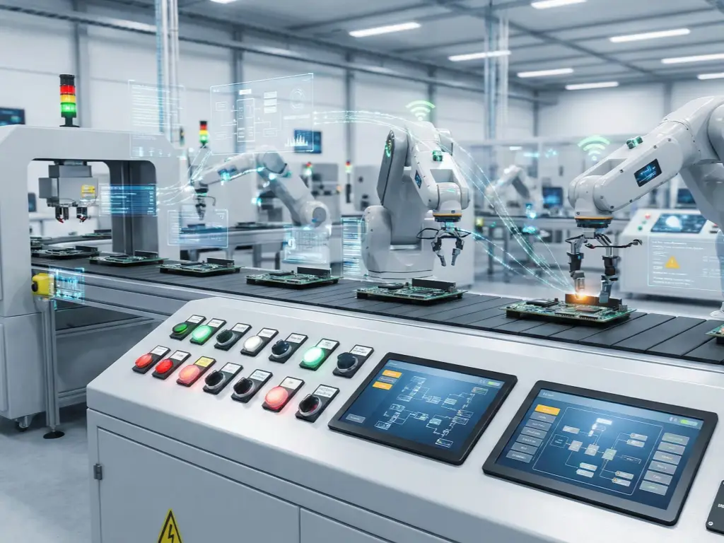
Future Outlook: Miniaturization and Integration in IoT Systems
As we transition into Industry 4.0, the role of the electromechanical switch is evolving from a “dumb” component to an integrated part of a “smart” system.
- Miniaturization: As wearable industrial technology and miniaturized robotics become a reality, the need to have switches that are “sub-miniature” and “ultra-miniature” is on the increase. These require advanced material science to maintain current-carrying capacity while reducing physical volume.
- Haptic Feedback Engineering: In high-end medical and automotive systems, the “sound” and “feel” of a switch are being designed to give the user a particular psychological feedback, which improves the user experience.
- IoT-Enabled Switches: Switches with inbuilt diagnostic features are coming up. These “Smart Switches” have the ability to measure their own contact resistance and temperature and transmit a signal to a central PLC or cloud-based maintenance system before the component fails. This changes maintenance to be “Reactive” to “Predictive”.
- Sustainability: Future manufacturing will focus on “Circular Economy” switches, using halogen-free plastics and recyclable precious metals, ensuring that industrial automation does not come at the cost of environmental health.
With these basics, categorizations, and technicalities, engineers can be able to make sure that their designs are not only practical but also designed to withstand the long-term challenges of the contemporary world. The lowly electromechanical switch is still an important component in the chain of human-machine communication whether you are creating a simple control box or a complex automated assembly line.


