












ما هو سكة DIN؟
A سكة DIN وهو سكة تثبيت معدنية موحدة تُستخدم داخل الصناديق الكهربائية وخزانات التحكم لتثبيت قواطع الدائرة، ومصادر الطاقة، والمرحلات، وكتل التوصيل، ووحدات التحكم المنطقية القابلة للبرمجة (PLC)، وغيرها من معدات التحكم الصناعية. وبدلاً من حفر ثقوب تثبيت منفصلة لكل مكون، يقوم المهندسون بتثبيت الأجهزة على السكة مباشرةً — مما يوفر الوقت والمساحة، ويجعل إجراء التعديلات المستقبلية أمراً سهلاً.
ويعود الاسم إلى المعهد الألماني للمعايير — المعهد الألماني للتقييس. ما بدأ كحل هندسي ألماني في عام 1928، تم تطويره بشكل مشترك بين شركة «فينيكس إلكتريكال سبلاي» وشركة المرافق «آر دبليو إي»، تم تحسينه خلال خمسينيات القرن العشرين ليصبح المقاطع المعدنية التي نستخدمها اليوم، ثم تم اعتمادها في نهاية المطاف كمعايير دولية في إطار اللجنة الكهروتقنية الدولية (IEC).
تخيل أن سكة DIN هي بمثابة الهيكل الأساسي للوحة التحكم. فهي توفر الدعم الميكانيكي فقط — فهي ليست مصممة لحمل التيار الكهربائي كقضيب توزيع، على الرغم من أنها يمكن أن تعمل كوصلة تأريض للهيكل عند ربطها بشكل صحيح. ويُقدَّر أن ما لا يقل عن 70% من المكونات الموجودة داخل خزانة التحكم الصناعية النموذجية يتم تركيبها على سكك DIN. ولولا هذه القطعة البسيطة من المعدن المشكّل، لكان بناء اللوحات أبطأ وأكثر ضخامة وأقل نمطية بكثير.
أنواع قضبان DIN وأبعادها
السؤال الأول الذي يطرح بعد “ما هذا؟” هو دائمًا “ما النوع الذي أحتاجه؟”. تعتمد الإجابة على ما تريد تثبيته — وبالنسبة لـ 90% من الاستخدامات، هناك إجابة واحدة واضحة. وقبل الخوض في تفاصيل كل نوع، إليك الإطار العام: المكونات هي التي تحدد مسار السكة. تحقق من مواصفات التثبيت الخاصة بأي جهاز صناعي تقوم بتركيبه — فهي ستوضح لك الشكل الذي صُمم الجهاز من أجله.
سكة «توب هات» TS35 — المعيار الصناعي
إذا مررت بجانب أي لوحة تحكم في أي مصنع في أي قارة، فمن شبه المؤكد أن القضيب الذي ستراه هو من طراز TS35 — بعرض 35 ملم ومقطع عرضي مميز على شكل قبعة. وهو واجهة التثبيت العالمية لمكونات التحكم الصناعية الحديثة.
يتوفر الطراز TS35 بنسختين مختلفتين من حيث العمق ضمن اللجنة الكهروتقنية الدولية 60715. المعيار TH35-7.5 يبلغ عرضه 35 ملم وعمقه 7.5 ملم، وهو يتوافق مع الغالبية العظمى من أجهزة التحكم: قواطع الدائرة المصغرة (MCBs)، ووحدات المعالجة المركزية (CPU) لوحدات التحكم المنطقية القابلة للبرمجة (PLC) ووحدات الإدخال/الإخراج (I/O)، وكتل التوصيل، والمرحلات النحيفة، ومحولات الإشارات، ومصادر الطاقة القياسية المثبتة على سكة DIN. وعندما تزداد أوزان المكونات — مثل الملامسات الكبيرة، أو مصادر الطاقة متعددة المخرجات التي تتجاوز قدرتها 240 واط، أو التركيبات المعرضة للاهتزاز المستمر — فإن العمق الأكبر TH35-15 (35 × 15 مم) يوفر الصلابة الإضافية المطلوبة. وهناك قاعدة عامة عملية: إذا كان وزن مكون واحد يزيد عن كيلوغرام واحد تقريبًا، أو إذا كان من المقرر تركيب الخزانة على آلة متحركة، فيجب استخدام القضيب الذي يبلغ عمقه 15 مم.
أحد المفاهيم التي يجدر فهمها هو نظام عرض الوحدات النمطية. تتبع الأجهزة المصممة لقضبان TS35 مسافة تباعد معيارية حيث 1 وحدة (1M) تساوي 18 ملم. يشغل قاطع الدائرة الأوتوماتيكي (MCB) أحادي القطب مسافة 1M (18 مم)، بينما يشغل القاطع ثلاثي الأقطاب مسافة 3M (54 مم)، وقد يمتد قاطع الدائرة المنطقي المدمج (PLC) على مسافة 4M (72 مم). يتيح هذا النظام لمصممي اللوحات الكهربائية تخطيط الترتيبات من خلال عد الوحدات — دون الحاجة إلى شريط قياس.
تتوفر قضبان TS35 في مثقوب (مثقوبة مسبقًا بفتحات للتثبيت) و غير مثقوب الإصدارات. يُسهّل القضيب المثقوب التثبيت على اللوحة الخلفية لأن الفتحات تعمل أيضًا كفتحات للبراغي؛ أما القضيب غير المثقوب فيوفر سطحًا أكثر أناقة عند استخدام حوامل تثبيت منفصلة.
سكة «TS15» المصغرة على شكل قبعة عالية
عندما تكون مساحة الخزانة محدودة — مثل صندوق التوصيلات الصغير الحجم، أو عملية التعديل التحديثي في غلاف قديم ذات مساحة محدودة — فإن TS15 يُقدّم هذا القضيب بديلاً أصغر حجماً بعرض 15 ملم وعمق 5.5 ملم. ويتوافق القضيب TS15 مع معيار EN 50045 (BS 6273، DIN 46277-2)، وقد صُمم لاستخدامه مع المرحلات الصغيرة ووحدات واجهة المستشعرات وكتل التوصيل خفيفة الوزن.
لكن المقابل في ذلك هو سعة التحميل. لا ينبغي أن تحمل قضبان TS15 مكونات يتجاوز وزنها 0.5 كجم تقريبًا. إذا كان لديك المساحة الكافية، فإن TS35 هي الخيار الأفضل دائمًا — ولكن عندما يكون لكل مليمتر أهميته، فإن TS15 تحل مشكلة حقيقية.
القضبان من النوع C-Section و G-Type — التقليدية والمخصصة للأحمال الثقيلة
هذه هي القضبان التي ستجدها في التركيبات القديمة، وليس في التصاميم الحديثة. قضبان العملية القيصرية (الموحدة وفقًا للمعيار EN 50024 الملغى حاليًا) تتميز بمقطع عرضي متماثل على شكل حرف C بعرض 32 مم، وهي متوفرة بأربعة ارتفاعات: C20 (20 مم)، وC30 (30 مم)، وC40 (40 مم)، وC50 (50 مم). قضبان من النوع G (المعروفة سابقًا باسم EN 50035 وBS 5825 وDIN 46277-1) تتميز بتصميم غير متماثل على شكل حرف G — بعرض 32 ملم وعمق 15 ملم — حيث يتم تثبيت الجانب الأعمق في الأسفل بحيث تُعلَّق المعدات على الحافة العلوية وتدور لتستقر في مكانها.
وقد تم استبدال كلا النوعين بمعيار IEC 60715 TS35 فيما يتعلق بالتصميمات الجديدة. ومع ذلك، إذا كنت تقوم بصيانة أو تحديث معدات تم تصنيعها قبل أوائل العقد الأول من القرن الحادي والعشرين تقريبًا، فقد تجد لا تزال قضبان من النوعين C و G بداخلها. يجب أن تدرك أن العديد من المكونات الحديثة المدمجة لن تتناسب مع هذه المقاطع دون استخدام محولات.
المعايير التي تحدد مواصفات قضبان DIN
لو أن كل مصنع صمم نظام تثبيت خاص به، لما كان من الممكن تركيب قاطع كهربائي من شركة «سيمنز» على نفس السكة التي يُركب عليها موصل كهربائي من شركة «ألين-برادلي». والسبب في إمكانية ذلك — والسبب في أن سكة DIN أصبحت معيارًا عالميًا بدلاً من أن تظل مجرد ظاهرة ألمانية غريبة — هو التوحيد القياسي.
الوثيقة التأسيسية الحالية هي اللجنة الكهروتقنية الدولية 60715 (نُشرت تحت رقم EN 60715 في أوروبا)، وعنوانها الكامل هو أبعاد أجهزة التبديل والتحكم ذات الجهد المنخفض — التركيب الموحد على القضبان لتوفير الدعم الميكانيكي للأجهزة الكهربائية. تحدد الطبعة الحالية، التي نُشرت في عام 2017، المتطلبات الأبعادية والوظيفية التي تضمن أن أي مكون متوافق من أي مصنع يمكن تركيبه بأمان على أي سكة متوافقة، في أي مكان في العالم.
| قياسي | نوع السكة | الحالة | ملاحظات |
|---|---|---|---|
| IEC/EN 60715 | TS35 (35×7.5 / 35×15) | الحالي | المعيار العالمي؛ الذي حل محل جميع الإصدارات السابقة من المعيار EN 50022 |
| EN 50045 | عشرة بوصات، خُمس | الحالي | معيار السكك الحديدية المصغرة |
| EN 50022 | سكة TS35 ذات الحافة العلوية | ملغى | تم استبدالها بالمعيار IEC 60715 |
| EN 50035 | سكة من النوع G (G32) | ملغى | لم تعد تخضع للصيانة؛ مخصصة للمعدات القديمة فقط |
| EN 50024 | الولادة القيصرية (C20–C50) | ملغى | لم تعد تخضع للصيانة؛ مخصصة للمعدات القديمة فقط |
| EN 50023 | قبعة عالية بعرض 75 ملم | الحالي (المتخصص) | نادرًا ما توجد خارج نطاق المعدات المتخصصة |
إذا كنت ستتذكر معيارًا واحدًا، فليكن هذا المعيار اللجنة الكهروتقنية الدولية 60715. وهي تنظم قطاع السكك الحديدية الذي ينقل أكثر من 90% من المكونات الصناعية المثبتة على سكك DIN في العالم.
جودة مواد وتصنيع سكة DIN
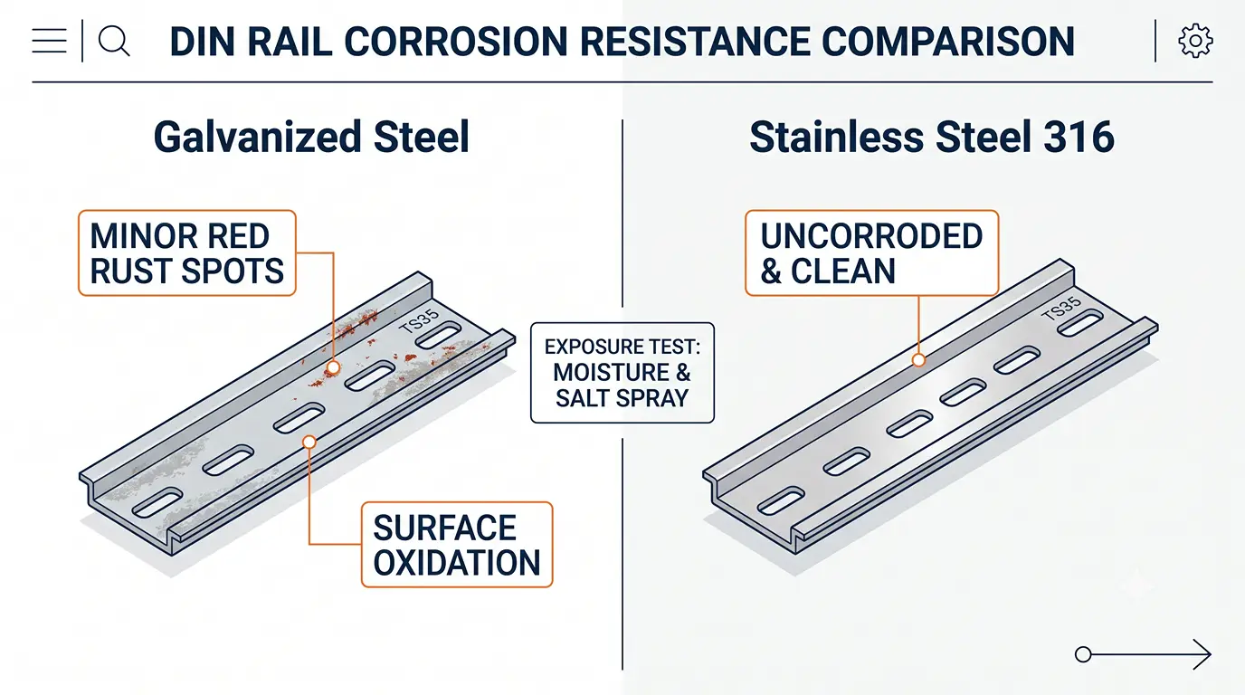
إليك نقطة غافل عنها معظم أدلة قضبان DIN: فهي تطلعك على الأنواع والأبعاد، لكن لا أحد تقريبًا يتحدث عن المادة التي يُصنع منها القضيب فعليًّا — واختيار المادة أكثر أهمية مما يدرك معظم المهندسين. فالمادة الخاطئة لن تمنع اللوحة من العمل في اليوم الأول. بل ستتعطل بصمت بعد ثلاث سنوات، عندما يؤدي التآكل إلى تثبيت قواطع الدائرة الكهربائية على القضيب بحيث يتعذر تحريرها.
هناك ثلاث فئات من المواد يجدر التعرف عليها، ويحدد الاختيار بينها مدة صلاحية السكة، والبيئات التي يمكنها تحملها، والتكلفة التي ستتحملها.
الفولاذ المجلفن — الخيار الافتراضي
يُعد ما يقارب 90% من قضبان DIN المباعة في جميع أنحاء العالم مصنوعة من الفولاذ الكربوني المدرفل على البارد والمغطى بطبقة واقية من الزنك. يتم تشكيل المادة الأساسية — التي عادةً ما تكون من الفولاذ من الدرجة DC01 أو DX51D (التصنيف الأوروبي) أو Q195/Q235 (المعيار الصيني) — على شكل مقطع «قبعة» أو «C» أو «G» بسمك يتراوح بين 1.0 و1.5 ملم، ثم يتم طلاءها كهربائيًا بطبقة من الزنك بسمك يتراوح بين 5 و12 ميكرومتر.
تقوم تلك الطبقة الرقيقة من الزنك بدور رئيسي في مقاومة الصدأ. ففي بيئة صناعية داخلية قياسية — مثل أرضية مصنع يتم التحكم في مناخها، أو غرفة الكهرباء في مبنى تجاري — يمكن أن تدوم سكة DIN المجلفنة بسهولة من 15 إلى 20 عامًا دون أن تتعرض لتآكل ملحوظ. فالزنك يضحي بنفسه كيميائيًا كهربائيًّا قبل أن يتأكسد الفولاذ الموجود تحته.
تكمن نقاط ضعف الفولاذ المجلفن في التعرض للرطوبة والمواد الكيميائية. ففي الأماكن المغلقة الخارجية، والمنشآت الساحلية، ومصانع تجهيز الأغذية التي تتطلب إجراءات غسل، أو أي بيئة تحتوي على كلوريدات محمولة في الهواء، تتآكل طبقة الزنك التي يتراوح سمكها بين 5 و12 ميكرومتر في غضون سنوات بدلاً من عقود. ويبلغ المعيار القياسي لاختبار رش الملح للقضبان DIN المطلية كهربائيًا 48 إلى 96 ساعة من رش الملح المحايد (NSS) — وهو ما يعتبر كافياً للاستخدام الداخلي، لكنه غير كافٍ للبيئات القاسية.
الفولاذ المقاوم للصدأ — للبيئات القاسية
عندما تصبح بيئة التركيب قاسية — مثل المنصات البحرية، أو غرف الأبحاث الصيدلانية النظيفة، أو محطات معالجة مياه الصرف الصحي، أو أي مكان يقع على بعد كيلومتر واحد من المياه المالحة — فإن سكة DIN المصنوعة من الفولاذ المقاوم للصدأ تتوقف عن كونها خيارًا متميزًا لتصبح ضرورة لا غنى عنها.
هناك نوعان رئيسيان من الدرجات يهيمنان على تطبيقات القضبان الصناعية من نوع DIN. AISI 304 يتحمل الفولاذ المقاوم للصدأ (18–20% كروم، 8–10.5% نيكل) معظم البيئات المسببة للتآكل غير المحتوية على الكلوريد، ويوفر متانة ممتازة في مجالات تصنيع الأغذية والمشروبات والمعالجة الكيميائية العامة. AISI 316 يُضاف إلى سبائك الفولاذ المقاوم للصدأ 2–3% من الموليبدينوم، وذلك تحديدًا لمقاومة التآكل النقطي الناتج عن الكلوريدات — وهذه هي الدرجة المطلوبة للاستخدام في البيئات البحرية، والمنشآت الساحلية، وأي تطبيق ينطوي على التعرض لرذاذ الملح أو مياه البحر.
لا تحتوي قضبان DIN المصنوعة من الفولاذ المقاوم للصدأ عادةً على أي طلاء سطحي إضافي — فالمادة نفسها هي التي توفر الحماية من التآكل. في اختبار رش الملح، يمكن أن يتحمل سكة DIN المصنوعة من الفولاذ المقاوم للصدأ التعرض لاختبار NSS لمدة تزيد عن 200 ساعة دون ظهور صدأ ملحوظ، مقارنةً بالفترة التي تتراوح بين 48 و96 ساعة التي عادةً ما يتحملها الفولاذ المجلفن. الزيادة في التكلفة حقيقية — توقع أن تدفع ما يقارب ثلاثة إلى خمسة أضعاف سعر السكة المجلفنة المكافئة — ولكن في بيئة تآكلية، تمنحك هذه الزيادة في التكلفة عمر خدمة يبلغ 20 عامًا بدلاً من دورة استبدال مدتها 3 أعوام.
الألومنيوم والنحاس — التطبيقات المتخصصة
وهناك مادتان تكملان الخيارات المتاحة، على الرغم من أن أيا منهما لا يُستخدم عادةً في صناعة الألواح ذات الاستخدامات العامة. سكة DIN من الألومنيوم (عادةً ما تكون من سبيكة 6063-T5 مع تشطيب مؤكسد) يبلغ وزنها حوالي ثلث وزن الفولاذ — وهي ميزة مهمة في الطائرات ومركبات السكك الحديدية والمعدات المتنقلة حيث يُعتبر كل كيلوغرام ذا أهمية. وتوفر طبقة الأكسيد الطبيعية الموجودة عليها مقاومة جيدة للتآكل دون الحاجة إلى طلاء إضافي. سكة DIN نحاسية يُستخدم هذا النظام في مجال متخصص للغاية حيث يعمل السكة نفسها كقضيب توصيل أرضي، مستفيدًا من الموصلية الفائقة للنحاس — لكن التكلفة والقوة الميكانيكية المنخفضة تجعله غير عملي للاستخدام العام في عمليات التثبيت.
بالنسبة لتطبيقات 99%، فإن الخيار ثنائي: الفولاذ المجلفن للوحات التحكم الداخلية، والفولاذ المقاوم للصدأ لأي شيء معرض للرطوبة أو المواد الكيميائية.
كيفية تركيب سكة DIN بشكل صحيح
إن معرفة نوع سكة DIN التي يجب شراؤها يمثل نصف الحل. أما تركيبها بشكل صحيح — أي قصها إلى الطول المطلوب دون التسبب في أي خطر على السلامة، وتثبيتها بشكل مستوٍ وبالمسافة المناسبة، وتأريضها بحيث توفر الحماية الفعلية للأشخاص — فهو ما يحدد جودة اللوحة.
ثلاث مراحل، لكل منها مجموعة من التفاصيل غير القابلة للتفاوض.
قطع القضيب وتجهيزه
عادةً ما تأتي قضبان DIN بأطوال قياسية تبلغ مترًا واحدًا أو مترين، وتتمثل مهمتك الأولى في قصها لتناسب اللوحة الخلفية للعلبة. اختيار الأداة أقل أهمية من التقنية المستخدمة: المنشار اليدوي ذو الشفرة ذات الأسنان الدقيقة (24–32 سنًا في البوصة) مناسب للأعمال العرضية؛ أما المنشار الشريطي فيعطي قطعًا أنظف وأكثر استقامةً لأعمال الإنتاج؛ أما المطحنة الزاوية المزودة بقرص قطع فهي سريعة ولكنها تولد حرارة قد تتسبب في تلف طلاء الزنك بالقرب من حافة القطع. تُنتج مقصات قضبان DIN المخصصة أفضل النتائج من حيث الدقة، لكن تكلفتها لا تبرر شرائها إلا في ورش تصنيع الألواح ذات الحجم الكبير.
هناك ثلاث قواعد تميز القص الاحترافي عن القص الخطير. أولاً, ، ضع علامة على خط القطع باستخدام مربع — فحتى لو انحرف القطع بمقدار درجتين فقط عن الوضع العمودي، فسوف يتسبب ذلك في أن يستقر القضيب بشكل مائل على اللوحة الخلفية. ثانياً, ، قم بإزالة الحواف الخشنة من كل حافة مقطوعة. فالحافة الخشنة الحادة الناتجة عن قطع المنشار قادرة على قطع عازل الأسلاك وجلد الإنسان بنفس الكفاءة — ويستغرق إجراء بضع تمريرات بملف ذي أسنان دقيقة أو أداة يدوية لإزالة الحواف الخشنة عشر ثوانٍ ويقضي على هذا الخطر. لا تستخدم أبدًا قرص الصقل لإزالة الحواف الخشنة؛ فحرارة الاحتكاك تحرق الطلاء الزنكي وتؤدي إلى ظهور بقعة فولاذية مكشوفة ستصاب بالصدأ في غضون أشهر. ثالثًا, ، تحقق من الطول النهائي مع تفاوت مسموح به يبلغ ±0.5 مم — فالسكة المقطوعة بطول أقصر من اللازم تترك فجوة في النهاية، أما السكة المقطوعة بطول أطول من اللازم فلن تتناسب مع المكان.
التركيب، والتباعد، والتخطيط
بعد قص القضيب إلى الطول المطلوب، قم بتثبيته على اللوحة الخلفية للعلبة باستخدام براغي تمر عبر فتحات التثبيت الموجودة في القضيب. احرص على توزيع مسامير التثبيت بمسافة تتراوح بين 200 و250 ملم على طول القضيب، مع وضع برغي على الأقل في كل طرف — فالطرف غير المدعوم من القضيب سينثني تحت وزن المكونات، مما يؤدي في النهاية إلى إجهاد مشابك التثبيت الخاصة بكل جهاز متصل به. استخدم مستوى مائي أثناء التثبيت. فالسكة DIN التي تنحرف ولو قليلاً تخلق منحدرًا قد تنزلق المكونات عليه ببطء تحت تأثير الاهتزازات، كما تتعرض كتل التوصيل الموجودة على سكة مائلة لقوة تثبيت غير متساوية.
بين صفوف قضبان DIN، اترك مساحة خالية تتراوح بين 50 و100 ملم لمجرى الأسلاك (القناة). يقوم المجرى بنقل الأسلاك الميدانية عبر اللوحة، والتقليل من مساحة المجرى يؤدي إلى ازدحام القنوات وصعوبة الصيانة وتراكم الحرارة. فوق المكون الأطول على كل سكة، اترك مسافة لا تقل عن 25 إلى 50 ملم قبل القناة أو السكة التالية — فهذه هي المساحة اللازمة لتركيب المكونات وفكها دون أن تتعارض مع الهياكل المجاورة.
تحتاج الأجهزة المولدة للحرارة — مثل وحدات تزويد الطاقة، والموصلات الكهربائية، ومرحلات الحالة الصلبة — إلى مساحة للتبريد. اترك فجوة هوائية تتراوح بين 5 و10 ملم بين هذه المكونات والمكونات المجاورة لها. وفي كل تصميم للوحة، خصص ما بين 20 و25 في المائة من إجمالي طول القضبان كمساحة فارغة للتوسع المستقبلي. تبدو اللوحة المملوءة بالكامل مرتبة، لكنها تفرض إعادة عمل مكلفة عندما يضيف العميل معدات بعد عامين.
التأريض وموانع النهاية
أخطر افتراض في مجال تصنيع اللوحات الكهربائية هو الاعتقاد بأن تثبيت سكة DIN على لوحة خلفية معدنية يؤدي تلقائيًّا إلى تأريضها. وهذا ليس صحيحًا. فالطلاء، والطلاء الأنودي، والطلاء بالزنك، وطبقات الأكسيد، كلها تعمل كعوازل كهربائية بين السكة واللوحة الخلفية. وحتى لو أظهر جهاز القياس المتعدد وجود استمرارية في حالة السكون، فإن هذا المسار قد يفشل في حالة حدوث تيار عطل.
والطريقة الصحيحة واضحة تمامًا: تركيب موصل تأريض مخصص — بحد أدنى 2.5 مم² من النحاس وفقًا للمعيار IEC 61439-1 — من سكة DIN إلى قضيب التوصيل الأرضي للصندوق، باستخدام لوحة توصيل أرضية مخصصة لسكة DIN مزودة بملامس زنبركي معدني مدمج يخترق الطلاء السطحي للسكة. وتتميز هذه الملامسات بترميز لوني باللونين الأخضر والأصفر لتسهيل التعرف عليها على الفور.
ومن الأمور التي لا تقبل التفاوض أيضًا: علامات نهاية السطر (وتُعرف أيضًا باسم المشابك الطرفية أو الدعامات الطرفية) عند طرفي كل صف من المكونات. فبدونها، قد تنزلق الأجهزة على طول السكة أثناء النقل، أو تحت تأثير الاهتزازات الصادرة عن الآلات المجاورة، أو ببساطة بسبب دورات التمدد والانكماش الحراري. يكلف زوج من المثبتات الطرفية بضعة دولارات. أما العثور على وحدة تحكم منطقية قابلة للبرمجة (PLC) انزلق من على سكة التثبيت بسبب الاهتزازات وتسببت في تمزق أسلاكها الميدانية أثناء النقل، فيكلف مئات الدولارات من وقت استكشاف الأعطال وإصلاحها — فضلاً عن الإضرار بسمعتك. تتطلب كل من معايير UL 508A و IEC تثبيتًا ميكانيكيًا عند طرفي كل مجموعة مكونات مُركبة.
افعل
لا تفعل
ما الذي يمكن تركيبه على سكة DIN؟ دليل التطبيقات والاختيار
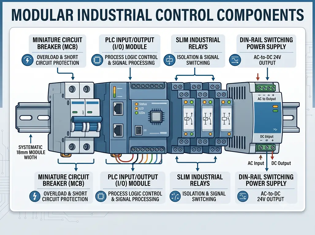
كل ما تم تناوله حتى الآن يقودنا إلى سؤال واحد: ما الذي يتم تركيبه فعليًّا على هذه القضبان؟ الإجابة المختصرة هي أن قضيب DIN يُعد العمود الفقري لنظام التحكم الصناعي الحديث — ويوضح الجدول التالي فئات المكونات الأكثر شيوعًا الموجودة على قضبان DIN في جميع أنحاء العالم.
| نوع المكون | أمثلة نموذجية | العرض القياسي | ملاحظات |
|---|---|---|---|
| قواطع الدائرة المصغرة (MCB) | قواطع كهربائية أحادية/ثنائية/ثلاثية الأطراف | 18–54 ملم (1–3M) | المكون الأكثر انتشارًا على سكة DIN |
| تبديل إمدادات الطاقة | وحدات تزويد الطاقة 24 فولت تيار مستمر المثبتة على سكة DIN، 15 وات – 480 وات | 32–120 ملم | الشبكة الكهربائية الرئيسية لخزانة التحكم؛ يجب ترك مسافة كافية للتبريد |
| أجهزة التحكم المنطقي القابلة للبرمجة | حاملات وحدة المعالجة المركزية + الإدخال/الإخراج القابلة للتجميع | يختلف حسب العلامة التجارية/الطراز | يتم تثبيت وحدة المعالجة المركزية (CPU) ووحدات التوسعة على نفس القضيب |
| المرحلات | الكهروميكانيكية والحالة الصلبة | 6–22 ملم لكل مرحل | التركيبات عالية الكثافة — انتبه إلى ارتفاع درجة الحرارة |
| الكتل الطرفية | مرور، تأريض، مزود بفتيل أمان، قاطع تيار | 5–12 ملم لكل كتلة | تصنيع شرائط التوصيل بالطول المطلوب بالضبط؛ إمكانيات تكوين لا حصر لها |
| المقاولون | مفاتيح التوصيل للتيار المتردد والتيار المستمر | 45–90 ملم | المكونات الثقيلة؛ استخدم سكة بعمق 15 مم إن أمكن |
| مُعدِّلات الإشارات | عوازل تناظرية، أجهزة إرسال درجات الحرارة | 6–22 ملم | خفيف الوزن؛ متوافق مع سكة TS15 في المساحات الضيقة |
عندما تكون مستعدًا لاختيار سكة DIN ومكوناتها لمشروع ما، فإن خطوات اتخاذ القرار تكون بسيطة. أولاً، تأكد من نوع السكة — في 99% من الحالات، ستحتاج إلى سكة TS35/7.5 من الفولاذ المجلفن ذات الشقوق. ثانيًا، قم بمطابقة المادة مع البيئة: تتطلب التركيبات الداخلية والمكيفة مناخيًا استخدام الفولاذ المجلفن؛ بينما تتطلب التركيبات الخارجية أو القابلة للغسل أو الساحلية استخدام الفولاذ المقاوم للصدأ. ثالثًا، اشترِ الملحقات في نفس الوقت — فالموانع الطرفية ومطاريف التأريض ومعدات التثبيت هي عناصر صغيرة قد تتسبب في تأخيرات كبيرة إذا نسيت شراءها.
يتطلب اختيار المكونات التي تُركب على القضيب — ولا سيما وحدة تزويد الطاقة، التي تُعد العنصر الأكثر أهمية في أي لوحة تحكم — انتباهًا دقيقًا. ابحث عن نطاق جهد دخل واسع (نطاق كامل من 85 إلى 264 فولت تيار متردد يعني أن وحدة تزويد الطاقة نفسها تعمل على أي شبكة كهربائية في جميع أنحاء العالم)، وشهادات السلامة المعترف بها (CE، RoHS، UL عند الحاجة)، ومُصنِّعًا يتمتع بمجموعة منتجات واسعة بما يكفي لتغطية احتياجاتك الكاملة من الطاقة من مصدر واحد.
تم إعداد هذا الدليل بالاستناد إلى المعيار IEC 60715:2017، والوثائق التاريخية لمعايير DIN/EN، بالإضافة إلى الخبرة العملية لمصنعي اللوحات الكهربائية في جميع أنحاء العالم.
المراجع: المساهمون في ويكيبيديا. “سكة DIN”. ويكيبيديا. · اللجنة الكهروتقنية الدولية. “IEC 60715:2017”. · OMCH. “مصدر الطاقة ذو الوضع التبديلي”.” omch.com · OMCH. omch.com



 English
  Arabic
  Turkish
  Russian
  Spanish
  French
  Indonesian
  Portuguese
  Thai
Thai  Vietnamese