


In regards to industrial automation, the control system is one of the most important factors to consider. However, you cannot control something unless you can measure it first. Encoders and resolvers perform the same basic function. They act as the feedback device of the servo motors, converting the mechanical motion of the shaft from rotary motion to electrical signals that can be consumed and understood by the drive controller. In applications ranging from robotic arms to electric vehicles, the selection of one of these two devices will determine not just the devices ability to function accurately, but also the devices ability to function reliably.
Operating Principles
Selecting the ideal component for each function requires us to examine the driving physics. The key differences between encoder vs resolver lie in how one senses motion: one is through electromagnetism, the other through light.
Resolvers: Analog Rotary Transformers
A resolver is a product from a time when the mechanical components needed to be durable and rugged. It is, in fact, a rotary transformer. A motor resolver comprises two parts: a stator, which is stationary, and a rotor, which spins with the motor shaft. What makes these parts unique, however, is the fact that they do not contain any circuit boards, solder, or silicon. The only components that they contain are copper windings (or coils), iron laminations, or a metal case.

In some designs, frameless resolvers are used to save space by mounting directly to the motor. Resolvers function via electromagnetic induction. The rotor windings are sent a reference AC signal, and as the rotor spins, one signal gets induced across the secondary windings. The secondary windings are positioned at 90 degrees across the stator and are meant to measure the angular position of the rotor.
Then, one secondary winding outputs a voltage that is proportional to the sine of the angle, while the other sine is proportional to the cosine. Based on the sine and cosine outputs, the current rotor position is extracted by the controller. This estimation is done along a continuum with no digital processing involved, producing an analogue signal.
Encoders: Digital Photoelectric Sensing
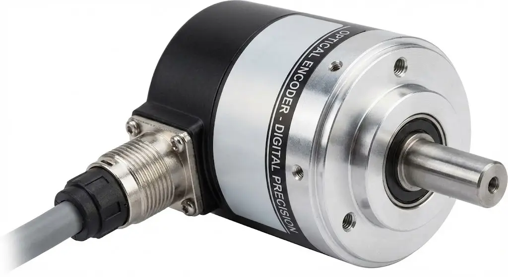
If the resolver is an analog workhorse, the optical encoders are digital precision instruments. Their operation is based on the interruption of light. Inside a rotary encoder, you will find a code disk—typically made of glass or high-grade plastic—mounted to the rotating shaft. This disk is etched with thousands of microscopic lines, creating a pattern of transparent and opaque slots. An LED light source sits on one side of the disk, and a photodetector array sits on the other.
As the disk spins, it chops the beam of light into rapid flashes. The sensor detects these flashes and converts them into electrical pulses. Internal electronics (an ASIC chip) immediately process these pulses into a clean digital output—usually a series of square waves (0s and 1s).
The optical encoder provides a direct digital language that modern controllers speak natively, offering high-resolution feedback that breaks a single rotation into millions of precise counts. The optical encoder provides a direct digital signal that modern controllers speak natively, offering high resolution feedback that breaks a single rotation into millions of precise counts. This creates a distinct advantage over simple incremental encoders which may require homing after power loss.
You could compare encoders and resolvers like this: resolvers function like traditional, mechanical wrist watches. They’re constructed from layers of intricate, heavyweight springs and gears (copper and iron). They’re built to last and rely purely on mechanical, physical principles. An optical encoder, in contrast, is like a smartwatch. These modern marvels are packed with microprocessors, sensors, and all sorts of modern electronics. They’re incredibly feature-rich and stand to be more precise. That is, until you smash them against a rock. Not only will the sensors fail, but the code disk will likely crack from the inertia of a heavy impact.
Resolver vs Encoder: Key Performance Specifications
In order to proceed from theory to engineering, we need facts, statistical facts to be specific, as evidenced in the following specifications comparison of common types of encoders and resolvers.
| Feature | Resolver | Optical Encoder |
| Operating Principle | Inductive (Analogue) | Photoelectric (Digital) |
| Max Operating Temp | 155°C to 200°C+ | 85°C to 100°C (120°C rare) |
| Shock Resistance | High (200g+) | Low to Medium (50g – 100g) |
| Vibration Tolerance | Excellent (20g – 40g) | Fair (10g – 20g) |
| Max Speed (RPM) | Limited (10k – 20k RPM) | High (Often 100k+ RPM) |
| Resolution/Precision | Moderate (10-14 bit equivalent) | Very High (12-24+ bit) |
| Output Signal | Sine/Cosine AC Voltage | Digital Pulses (TTL, HTL) or Protocols (SSI, EtherCAT) |
| Electronic Failure Risk | Near Zero (Passive component) | Moderate (Active component) |
Data has clearly drawn a line. If one has an application where the motor must revolve at 50,000 RPM, the impedance features of a resolver will lead to signal deterioration, compelling you to, as the last option, an encoder. On the other hand, if 140°C is the temperature of the casing of your motor, then the silicon chips in an encoder will get burnt out. Therefore, the resolver sensor will be the only option.
What Makes Resolver and Encoder Stand Out?
The difference between a resolver vs encoder is not a question of one being better. It’s simply a question of surviving in a hostile environment (i.e., decidedly extreme temperatures) and underperforming or being precise and getting the job done.
The Case for Ruggedness (Resolver)
Not only is the resolvers vintage design obstruction of electronics a powerful advantage, but it also makes it the hand-down champ of extreme endurance. Because nothing can fail due to heat or radiation (i.e, harsh environments), the resolver stays at the top of environmental conditions.
- Temperature: A standard resolver operates continuously at temperatures around 155°C being put from them. Specialized models have even been designed to reach 200°C or more in high temperature environments, which stands to be the overriding limit. It’s simply a consequence of the insulation material and wire used in copper formations.
- Vibration and Shock: A resolver can withstand mechanical shocks (like above 200g) and heavy vibration. There are no shattering glass disks and no solder joints to break.
- Contaminants: Magnetic fields are not affected by oil, grease, moisture, or dust. A resolver can still work while flooded by oil. This allows for direct integration inside motor housings to monitor shaft position.
The Case for Precision (Encoder)
The more accurate data means an optical encoder will be less durable.
- Accuracy: The optical technology will have a much higher resolution. The encoder resolution is higher compared to a resolver. The resolver loses accuracy due to mechanical winding precision and signal noise. The optical encoder doesn’t have that problem and can reach a 20-bit resolution for high accuracy.
- Signal Clarity: The signal is digitized right away which means less exposure to EMI. So, compared to a resolver, optical encoders are more protected during transmission.
- Dynamic Response: For some applications, an optical encoder would be preferred to a resolver since it contains greater feedback density and achieves higher line counts for precise velocity control.
Beyond the Sticker Price: A Real-World Cost Analysis
When a procurement manager is reviewing the Bill of Materials (BOM), one of the most common forms of mistake is only comparing the cost of one sensor in the BOM. A wider view, one that is integrated, will lead to a better decision in the form of Total Cost of Ownership (TCO). In the context of a resolver vs encoder cost comparison, looking beyond the sticker price is essential.
In most cases, high quality optical encoder has a higher price, thus it is more expensive to manufacture compared to a standard resolver. A simple resolver appears to cost less on the shelf, therefore dominant in price.
The biggest risk lies in integration. A resolver outputs a “dumb” analog signal that your control system cannot read directly. Your drive needs to incorporate a Resolver-to-Digital (R/D) converter, which is frequently a premium feature on the servo drive or a costly add-on card. In addition, resolvers need costly multi-pair, twisted, and shielded cabling for long cable runs in order to preserve the corrupted analog signal from the noise.
On the other hand, an optical encoder outputs a usable digital signal. It connects easily to the standard inputs of almost any controller and does not need the expensive, specialized hardware and software to decode the signal or additional noise suppression. For this reason, optical encoders typically result in a lower overall system cost in general industrial automation applications as they simplify the architecture and overall design, assuming the hardware is more expensive.
Industry Applications: Resolver vs Encoder
The technical attributes we have discussed have resulted in a natural segregation of the market in the industry based on different needs.
Electric Vehicle Propulsion: The Case for Resolvers
When considering which electronic components can withstand the most extreme conditions, the traction motor of an electric vehicle (EV) is at the top of the list. The motor experiences pothole shocks, road vibrations, and high temperatures due to the high currents and sensor cooling, which is made worse by their being buried deep within the motor structure.

In these extreme conditions, the sensor is expected to perform its function reliably because doing otherwise can create a road hazard by rendering the EV inoperable. This explains why most EV manufacturers opt for resolvers: they can last in conditions where optical encoders would fail within minutes. Resolvers have been described as being constructed of a ‘tank’, their motor position feedback signal is steady as long as their motor shaft rotates.
CNC and Robotics: The Case for Optical Encoders
In Computer Numerical Control (CNC) machining and the six-axis robotics that perform it, survival is no longer the priority. Rather, that has been replaced by precision motion control on assembly lines.
- Surface Finish: A CNC machine’s feed rate profile must be accurate when cutting a smartphone mold. Any deviation from the programmed feed rate will cause ripples to form on the surface of the metal. Optical encoders ensure that the servo drive can make the necessary speed corrections to maintain a constant velocity.
- Positioning: A robotic arm must maintain sub-micron precision when landing a chip onto a circuit board. Achieving this level of holding accuracy is challenging to accomplish due to the resolver’s analog noise floor. For this level of automation, optical encoders offer the necessary stable control and accurate feedback loop.
Market Trends: The Rise of Magnetic Alternatives
Over the last several decades, the overwhelming binary choice of optical encoders and resolvers has been shown to be suboptimal according to the latest market studies. With advances in Hall Effect technology and AMR (Anisotropic Magnetoresistance), the industry has begun to favor Magnetic Encoders (and sometimes capacitive encoders) as a balanced compromise among types of encoders.
EV frontrunners like Tesla and BYD and motion control systems like Universal Robots and Yaskawa are industry frontrunners replacing heavyweight resolvers with miniaturized magnetic sensors. 10-20 bit magnetic feedback is achieving significant space reductions and cutting costs by a margin of 15% without undermining performance. This is proof that magnetic technology is the rational optimal solution for numerous use cases.
In aerospace, however, this changing of the guard is at odds with the pack. Due to the harsh nature of the use cases, the resolvers remain. Missions that involve thermal challenges, such as operating between -55°C and + 180°C, or require 0.1°C positioning accuracy or better, still utilize resolvers. Magnetic alternatives, while still unproven for mainstream use in flight-critical systems, are currently undergoing testing.
Selection Guide
In these cases, trade-offs steered by a set of parameters are at play in reaching the conclusion to make an informed choice. This encoder vs resolver does not rumor obsolescence, but rather describes the needed specialization. Make use of the 3-Step Decision Matrix here to determine the best feedback device for your motor and cut through the clutter in the process:
| Step | Decision Factor | Critical Question | If the Answer is YES | If Answer is NO |
| 1 | Temperature | Is the environment likely to exceed 120°C (248°F)? | Choose Resolver (No electronics to fail) | Proceed to Step 2 |
| 2 | Precision | Do you require nanometer positioning or zero-ripple velocity? | Choose Optical Encoder (Unbeaten glass scale accuracy) | Proceed to Step 3 |
| 3 | Environment | Is the area dirty, oily, or subject to high vibration? | Choose Magnetic Encoder (Durable & Cost-effective) | Choose Standard Encoder (Best balance of cost/performance) |
Now that you know exactly what you need, the only question left is where to get it without overpaying.
This is where OMCH steps in. Since 1986, we have proven that industrial reliability does not require a premium price tag. We are not just another vendor; we are a manufacturing engine serving over 72,000 customers across 100 countries, shipping 20 million units annually. With over 3,000 SKUs in stock—including a comprehensive range of high-precision encoders certified to CE and RoHS standards—we likely have the exact specification you are looking for. Why risk your budget on inflated brand names when you can get the same steady performance directly from the source?
Whether you need a rugged sensor for a heavy-duty application or a precision encoder for an automated line, stop guessing and start optimizing. Contact OMCH Support today for a free consultation or Browse Our Encoder Catalog to find the perfect fit for your next project.
FAQs
- Why use a resolver instead of an encoder?
Resolvers are chosen primarily for durability. Because they contain no onboard electronic components (chips, capacitors, or solder), they can withstand extreme temperatures (>155°C), heavy vibration, and radiation that would cause the delicate electronics inside an encoder to fail instantly.
- Is a resolver an absolute encoder?
Yes, a standard resolver acts as a single-turn absolute encoder (often compared to absolute encoders), providing absolute position data in an analog fashion. It outputs a distinct analog voltage for each unique position value during a 360°C rotation (providing absolute position). Once energized, it knows its position, but cannot keep track of other full rotations during power on without additional logic on the feedback electronics.
- Can I simply replace a resolver with an encoder?
In most cases, the answer is no. Each electronic interface on the resolver and encoder is very different; an encoder uses digital outputs and DC power while a resolver requires analog outputs and AC excitation. In the case of swapping devices, you will most likely need to change the servo drive or provide a costly signal converter in between.


