


The electronic diagram is an unforgiving paper. It is not just an implication of the way a machine ought to work; it is an agreement between the will of the engineer and the actuality of the factory floor. When such a contract is misinterpreted, it is not only a wiring error that will be the outcome, but it is also downtime, ruined tooling, or a safety violation.
At the center of these diagrams is the limit switch, a critical electromechanical device. It is the sensory organ of industrial automation, the device that converts mechanical position to electrical logic. However, the image of these devices is discontinued by geography and tradition. A drawing made in Stuttgart does not appear like a drawing made in Detroit. To manoeuvre in the international arena of industrial settings and electrical engineering, a person should be proficient in the graphic language of control.
This manual breaks down the confusion of the symbols of limit switches, and the lines and circles are once again converted into the mechanical truths they signify.
IEC 60617 vs. NEMA (JIC): Visualizing Global Symbol Standards
Being able to read a schematic requires knowledge of two different visual languages: the IEC standard (Europe/Asia) and the NEMA standard (North America). Although both describe the same electrical circuit behaviors regarding the electrical connection, the styles are completely different.
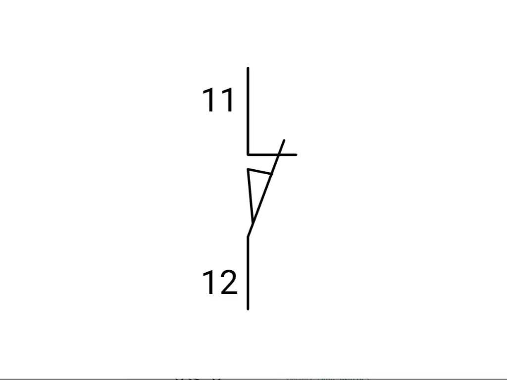
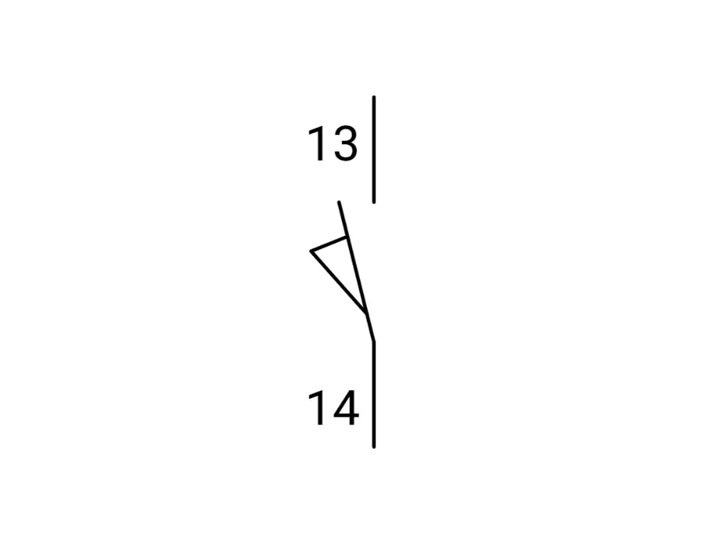
IEC: Approaching Visualization with Abstraction and Geometric Efficiency. IEC 60617 treats all components as abstract contact blocks and represents them with the same line. A limit switch, relay, or electrical switch would be the same vertical line, differentiated by an activator (bump, square, etc.). It focuses on the logic of the electrical signal, regardless of the voltage or volts involved.
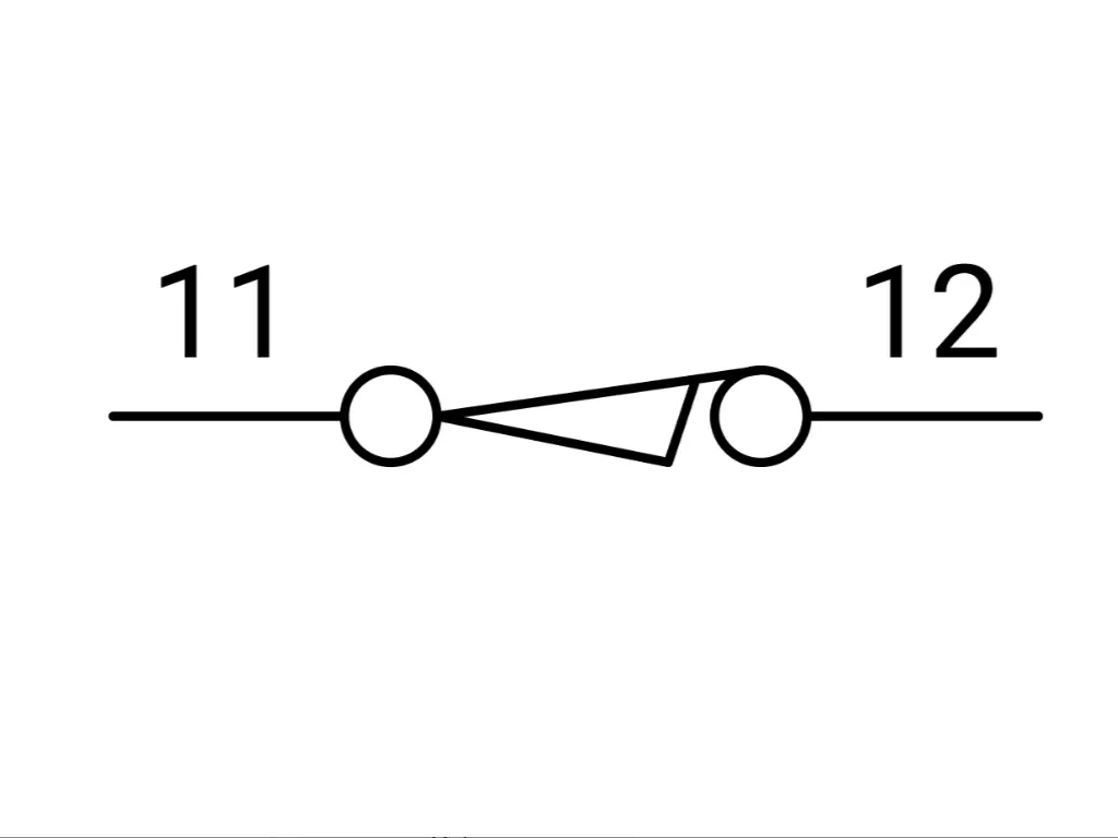
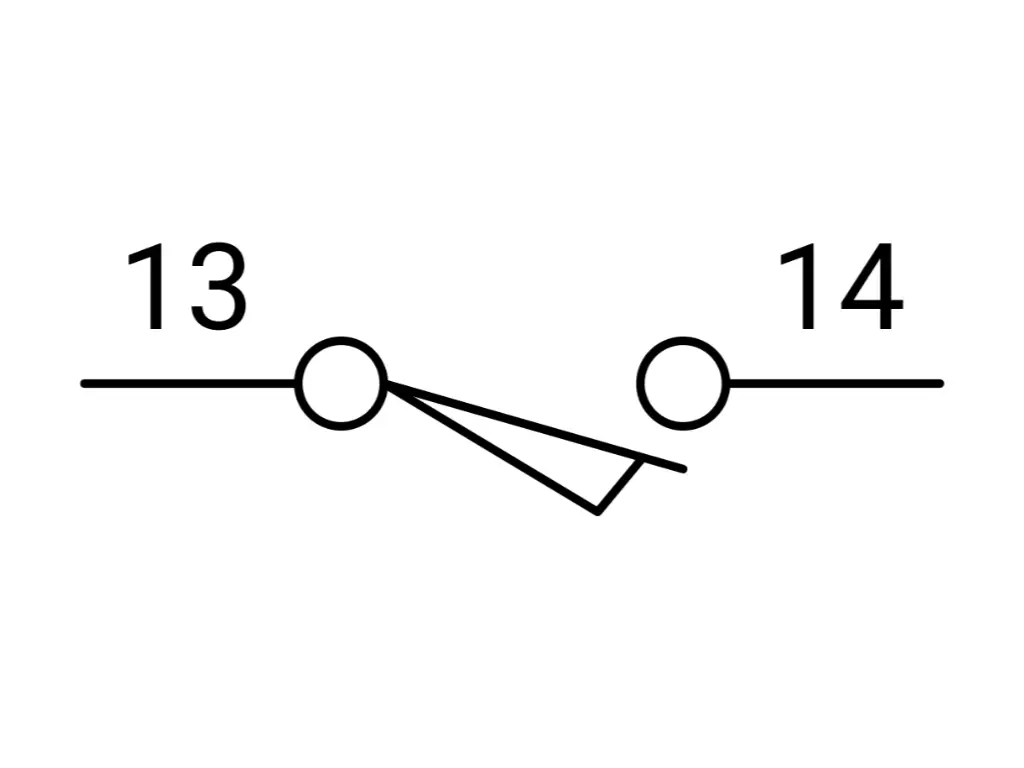
NEMA: Approaching Visualization with Illustration and Intuition.NEMA symbols are constructed to visually communicate the limit switch as a lever arm and a pushbutton as a plunger. Diagrams display abstract codes with the coordinative movement, serving as a visual interface for the ladder logic used in a control system. The symbol often hints at the physical terminals where a technician might solder or screw in the common terminal wire.
Decoding Contact States: NO, NC, and Held Positions
The terms “Normally Open” (NO) and “Normally Closed” (NC) are misleading in their simplicity. They imply an eternal condition of existence. As a matter of fact, the term “Normal” is used to describe a certain, hypothetical state: the switch on a workbench, not connected, not touched by any physical force, not affected by gravity.
Nevertheless, schematics do not represent elements on a workbench. They represent a set of contacts fitted in a machine. This leads to the very important, misconstrued notion of the Held position.
The Static Lie of the Schematic
A schematic is a snapshot of a machine in its original position (or “shelf state”). It is as though a photo of a runner in the starting blocks.
- NO (Normally Open): In the shelf state, the contacts are separated. Current cannot flow through this part of the limit switch. When actuator movement occurs, the contact closes.
- NC (Normally Closed): In the shelf state, the contacts touch. Current flows freely. As the target hits the actuator, the contact is broken and the control circuit is broken.
This is easy until the machine design requires a switch to be actuated before the machine even starts.
The “Held” State: Reading the Invisible Force
Consider a safety gate, which must be closed to use the machine. When the gate is closed (safe condition) the limit switch is pressed. If you wire a single pole Normally Open switch here, the closed gate pushes it closed, completing the circuit.
On the electrical drawing, how do you draw this? If you draw a standard “Closed” contact, a technician may think it is an NC switch. However, it is actually an NO switch that is being pressed. This distinction plays an important role in troubleshooting response time and logic errors.
Here the symbols of the Held come in:
- Held Closed: The symbol appears to be closed, but it includes a graphic indication (often a small wedge or cam under the switch arm) showing that an external force is keeping it that way. It informs the reader: I am a Normally Open switch, however, in the starting position of this machine, something is standing on me.
- Held Open: This is a Normally Closed switch, however, which is being forced open by the resting position of the machine.
The difference between detecting a faulty sensor and the machine simply being out of its home position is in the understanding of the switching action of the “Held” symbols. It separates the data readers from the system understanders.
| Function | IEC 60617 Symbol Logic | NEMA (North America) Symbol Logic | Physical Behavior |
| Normally Open (NO) | A vertical gap; a bar sits away from the terminals. | A gap with a horizontal arm below the terminal points. | Circuit is broken (OFF) until the switch is hit. |
| Normally Closed (NC) | A vertical line; a bar bridges the terminals. | A horizontal arm bridging the terminals, often drawn below the line. | Circuit is complete (ON) until the switch is hit. |
| Held Open | An NC symbol with a specialized mechanical cam graphic keeping it open. | The arm is drawn below the terminals but pushed down (open) by a wedge. | Wired as NC, but the machine’s home position presses it open. |
| Held Closed | An NO symbol with a cam graphic pushing it closed. | The arm is drawn below the terminals but pushed up (closed) by a wedge. | Wired as NO, but the machine’s home position presses it closed. |
Safety vs. Standard Symbols: Decoding the Positive Opening Icon
All clicks are not created equal. In the hierarchy of industrial controls, machine safety trumps function. This difference is directly coded in the symbols we operate with, namely, in the notion of Positive Opening (or Direct Opening Action).
We use springs in normal automation. A spring in the housing forces the electrical contacts into their original position when a limit switch plunger is released. But springs are fallible. They can snap, fatigue, or jam. Worse still, electrical contacts may weld. If a high current surge occurs just as a switch closes, the metal contacts may fuse. In an ordinary switch that uses a spring, the weld is stronger than the spring. The machine presupposes that the switch is closed, yet the contacts are stuck. The spring pushes in vain. The conveyor does not stop. The press comes down.
The Symbol of Authority: The Circle and Arrow
To avoid this disaster, the IEC 60947-5-1 Annex K stipulates the Positive Opening mechanism. This is schematically represented by a certain icon: a circle with an arrow inside, connected to the NC contact symbol.
This symbol is used to indicate a rigid mechanical connection between the external actuator and the internal electrical contact. The plunger and the point of contact separation are not connected by any resilient elements, such as springs. When the contacts weld, the pure force of the machine striking the limit switch will tear the weld open. It forces the circuit open, regardless of the contact’s desire to remain fused.
Contextual Usage
- Standard Symbol: Used for object detection, counting, or non-critical positioning (e.g., telling a programmable logic controller a robotic arm has reached the shelf).
- Safety Symbol (Positive Opening): Mandatory for safety interlock applications, emergency stops, and general safety purposes where failure means injury.
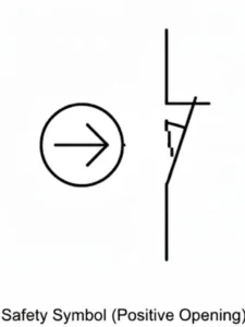
When reading a schematic, the presence of the arrow-in-circle tells you that this specific switch is a guardian, not just a counter. It dictates the durability and ruggedness requirements of the circuit.
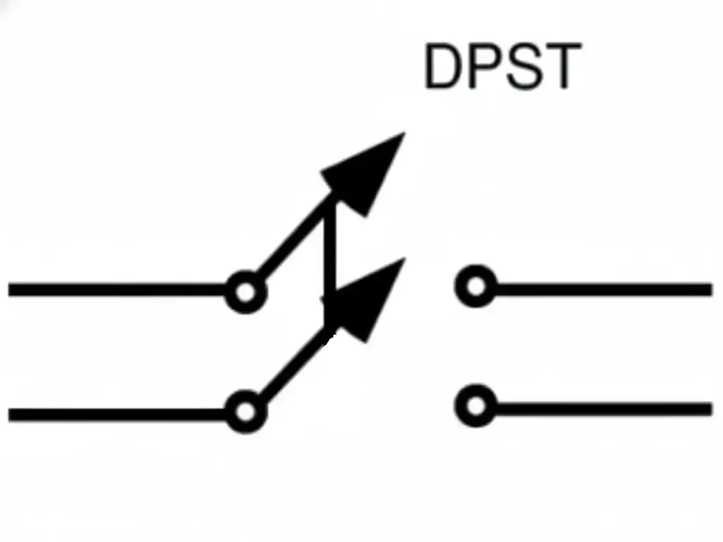
Double-Circuit Symbols: Optimizing Logic with 1NO+1NC Designs
In the early days of automation, single-pole switches (SPDT) were common. You had one common wire and switched it between open and closed. Among the various types of limit switches, modern, high-reliability automation has shifted decisively toward the Double-Circuit design, typically configured as 1NO + 1NC (One Normally Open + One Normally Closed).
The schematic representation of a double-circuit limit switch shows two distinct, electrically isolated lines controlled by the same mechanical link. This is not merely a doubling of wires; it is an exponential increase in logic capability, making it a vital part of a control system.
The Logic Advantage: Monitoring and Cut-off
Why have two circuits where one can perform the task? Since a single circuit cannot convey the entire truth.
The system uses Complementary Logic in a 1NO+1NC setup.
- The NC Contact (The Guard): This is often wired in series with the hardware power or the safety relay. When the motion of a machine part triggers the switch, this contact physically breaks the circuit, stopping the motor. It is the brute force stop.
- The NO Contact (The Informant): This is wired to the PLC’s digital input. When the limit is hit, this contact closes, sending a 24V signal to the controller saying, “I have arrived at position X.”
The controller is able to carry out self-diagnostics by comparing these two states. If the PLC detects the NO contact is closed, but the NC contact does not open (a logic mismatch), the system detects a fault (a broken wire, a welded contact, or a short circuit) and goes into a safe failure mode. This is a characteristic of the contemporary, strong system design, dual-channel feedback.
Internal Mechanism: Why Double Springs Matter
On the schematic, this appears as two individual switches connected by a dashed line. As a matter of fact, it is Galvanic Isolation. The two circuits have no electrical connection inside the switch. This enables one type of limit switch to switch between two entirely different voltage potentials, such as the NC contact is a direct cut-off of a 110V AC motor contactor, and the NO contact transmits a 24V DC signal to the logic controller.
This ability minimizes the number of components in the panel. Rather than installing two switches (one of them being a safety switch, the other a data switch), one, large, two-circuit limit switch can perform both functions more reliably. It makes the schematic less complex and makes a more verifiable physical installation, regardless of the type of actuator used.
Effective circuit design, however, relies on manufacturing depth. OMCH, leveraging 38 years of industrial experience, exemplifies this capability. Our 20-year veteran engineering team moves beyond standard catalogs to offer precise OEM/ODM customization—from optimizing circuit board designs and power outputs to tailoring packaging formats. This ensures the physical switch doesn’t just match the schematic’s logic but adapts to the specific constraints of the application, bridging the gap between theoretical design and rugged industrial reality.Contact OMCH https://www.omch.com/ today to define the exact logic and durability your project demands.
Symbol Complexity: SPDT, DPDT, and Snap Action Variations
As we move deeper into the schematic, the symbols develop more nuance. We encounter the distinctions of speed and pole count.
Snap Action vs. Slow Action Symbols
The motion of the machine is analog; it ramps up and slows down. But electrical logic prefers to be binary; it wants a clean 0 or 1.
- Slow Action: In a slow-action switch, the contacts move at the same speed as the actuator. When the machine presses the plunger slowly the contacts part slowly. This may result in arcing and inaccurate signals. The schematic representation of this is typically a straight line of simple form, to represent the contact bar.
- Snap Action: A snap action switch is a switch that stores energy in an internal spring. When the plunger (or lever arm) has reached a critical point, the contacts will instantly jump over, no matter how slowly the external plunger limit switches are moving.
| Feature | Slow Action Symbols | Snap Action Symbols |
| Visual Identifier | Straight Lines. Standard contact bars. | Triangle / Wedge. A geometric shape on the contact line. |
| Behavior Concept | “The Mirror” Contacts move at the exact speed of the actuator. | “The Instant” Contacts jump instantly once a trip point is reached. |
| Hysteresis | Low / None. Trip and reset points are nearly identical. | High. Distinct differential between the trip and reset points. |
| Best Application | Precise positioning where signal must match travel exactly. | Eliminating “chatter” from machine vibration; ensuring clean digital signals. |
In IEC schematics, Snap Action is often represented by a small triangle or wedge on the contact line itself. This is a subtle geometric addition that is a signal to the circuit designer. It means hysteresis – a discrepancy between the trip point and the reset point. This eliminates chattering, in which a switch is rapidly switched on and off when the machine vibrates around the trip point. The understanding of this symbol is the reason why a machine may be required to withdraw a few millimeters before the automation is reset.
SPDT vs. DPDT Configurations
The density of control is also shown in the schematic.
- SPDT (Single Pole, Double Throw): One input, two possible outputs. The symbol shows one common terminal branching into two.

- DPDT (Double Pole, Double Throw): Two inputs, four possible outputs.
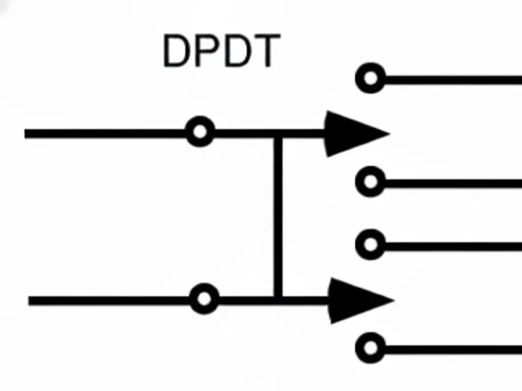
The DPDT symbol appears as two distinct SPDT symbols linked by a mechanical dashed line. Why use this? It allows for redundant safety channels (Channel A and Channel B), which are required for Cat 3 or Cat 4 safety architectures. Alternatively, it allows a single lever limit switch to control two independent machines simultaneously—when the gate closes, Machine A starts (NO contact closes) and Machine B stops (NC contact opens), with zero electrical interference between them. A lever or roller actuator can drive both poles simultaneously.
Interpreting Symbols in P&ID vs. Electrical Schematics
The electrical engineer is not the sole one mapping the plant. The Process Engineer develops P&IDs (Piping and Instrumentation Diagrams). In this case, the limit switch installation is not considered a circuit, but as a function.
The contact linkage or the terminal numbers will hardly be visible in a P&ID. Rather, you observe a bubble (a circle) attached to a valve or a cylinder.
- ZSO / LSO: Position Switch Open / Limit Switch Open.
- ZSC / LSC: Position Switch Closed / Limit Switch Closed.
- LSH (Level Switch High) / LSL (Level Switch Low): Used in tank logic.
The misunderstanding arises when the Process Engineer writes LSH on the P&ID, which presupposes a logic function (High Level Alarm), but the Electrical Engineer has to convert it into a physical device. Does “High Level” mean that the switch is wired Normally Open (closes on high) or Normally Closed (opens on high for fail-safe)?
The P&ID describes what (the process requirement, like detecting a moving object). The Electrical Schematic is the how (the wiring implementation). The translation key between these two documents is the limit switch symbol. A good engineer uses the P&ID to identify the logic goal (such as the limit of travel of an object or the status of overhead garage doors), and then chooses the right IEC/NEMA symbol (NO, NC, Held) to achieve that goal in a safe manner.
Quick Reference: Essential Limit Switch Symbol
To summarize, the ability to read these symbols is the ability to visualize the machine’s behavior before it is built.
- The Basics (State at Rest)
- NO (Normally Open):
—| |—(The gap represents the silence before the signal). - NC (Normally Closed):
—|/|—(The diagonal line represents the flow that must be interrupted).
- NO (Normally Open):
- The Dynamic States (Machine Logic)
- Held Closed: An NO switch, forced closed by the home position. Treat it as “NC” for continuity, but “NO” for replacement.
- Held Open: An NC switch, forced open by the home position.
- The Safety Critical (IEC 60947-5-1)
- Positive Opening:
—|/|—with a(→)symbol. - Meaning: Do not substitute with a generic switch. This circuit protects human life.
- Positive Opening:
- The Mechanism
- Snap Action: Look for the triangle/wedge on the contact line. Expect hysteresis.
- Slow Action: Straight lines. Expect the signal to mirror the speed of the machine.
The schematic is a map. The symbols are the legend. When read properly, you can work your way through the most complicated automation systems with the assurance that you are not only aware of the path that the wires follow, but also why they follow those paths.
To understand the physical mechanics that drive these symbols, explore our foundational guide on What is a Limit Switch?. Or, if you are troubleshooting a discrepancy between the diagram and reality, verify the component’s integrity with our practical tutorial on How to Test a Limit Switch.


