


What Is A Limit Switch?
A limit switch is one of the most common and essential electromechanical devices in industrial automation. In simple terms it is a sensor which transforms mechanical movement into an electrical signal.
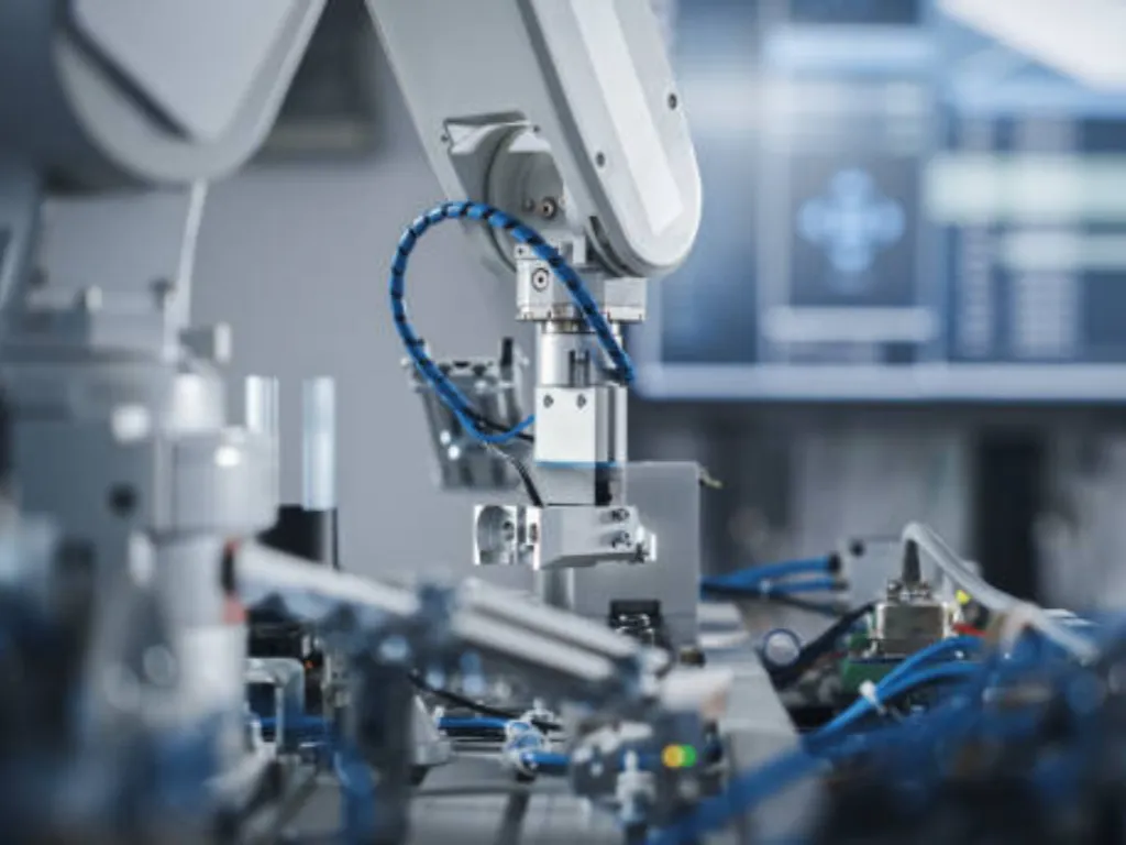
It is primarily used to sense when an object (a robotic arm, a box on a conveyor belt or a cylinder piston) has arrived at a specified physical location or limit of travel of an object. When the object contacts the switch’s actuator, the internal set of contacts quickly operate, changing the electrical circuit status—usually opening (Normally Closed, NC) or closing (Normally Open, NO) the circuit. This action sends a signal to the controller (like a PLC or relay).
Limit switches are common in automation due to three key benefits, namely, ruggedness, high reliability, and simplicity of installation. They are able to withstand extreme industrial conditions, including dust, moisture, oil and extreme mechanical shock. This renders them the choice position detection element in the industrial environment where high stability is essential.
How It Works: Motion to Signal
The core of a limit switch is its mechanical-electrical conversion mechanism. Although models and actuators differ, the basic principle is consistent:
- Normal State: When no external object is in contact, the switch set of contacts stay in their normal state. As an example, Normally Open (NO) contacts are open and Normally Closed (NC) contacts are closed.
- Actuation Begins: The moving object contacts and pushes the actuator (like a roller or plunger). This is the mechanical force which then acts on the internal spring mechanism.
- Snap Action Mechanism: Snap action mechanism is used in most industrial limit switches. As the actuator is moved to a given position (the operating point) the internal spring rapidly and abruptly alters the contact status. This rapid switching action is significant as it minimizes arcing and contact bouncing that contributes to the increased life of the switch.
- Signal Output: The change in contact status (NO closing, NC opening) completes the conversion from mechanical energy to electrical energy. This electrical signal is then sent to the PLC or other control circuit to trigger the next action or logic.
- Reset:As the object is pushed off the actuator the internal return spring forces the actuator and contacts to their original normal position. The switch is then prepared for the next detection cycle.
Types and Actuator Mechanisms
Although the fundamental concept of a limit switch remains the same, they are designed in different types of limit switches depending on the actuator and sensing method to suit the various applications.
Mechanical Limit Switches
They are the most widespread and are triggered by physical contact. Their name usually is based on the shape and movement of the actuator (the part that touches the target object):
| Actuator Type | Trigger Method and Application |
| Roller | The actuator has a roller end. It is suitable for scenarios where the object slides past and pushes the switch. It is commonly used on conveyor belts and cam mechanisms. |
| Plunger | This allows only vertical or straight-line pushing. It is suitable for short-travel positioning that requires high precision and repeated triggering. |
| Lever | It has a long or short lever arm. It uses leverage to amplify displacement. It is suitable for scenarios with low trigger force and large movement amplitude. |
| Whisker | It has a long, thin spring wire. It is sensitive to slight contact from any direction. It is often used to detect the presence of an object. |
Mechanical switches are direct, reliable, and produce a strong output signal. However, the downside is that they require physical contact, which causes mechanical wear. If you are troubled with selection, visit here to know more about the type of limit switch.
If you are troubled with selection, visit here to know more about limit switch types.
Non-Contact Limit Switches
These sensors also limit or detect position functionally. They do not, however, depend upon physical contact. These are commonly referred to as Proximity Sensors. They are used to substitute mechanical limit switches in high-frequency or where contact is prohibited:
- Inductive: Detects metallic objects using electromagnetic fields.
- Capacitive: Detects objects made of any material (metal, plastic, liquid) by sensing changes in capacitance, often related to absence of an object.
- Photoelectric: Detects objects using a light beam (through-beam, retro-reflective, or diffuse reflective types).
Click here to know more about types of proximity sensors to help with your selection.
Practical Installation & Wiring Tips
The reliability of an electrical switch depends heavily on correct installation and wiring. Wrong installation can lead to false triggers, high-frequency wear, or damage to the control system.
Contact and Wiring Basics
Limit switch contact configurations usually include:
- Normally Open (NO): The contacts are open when the actuator is not activated; they close when activated.
- Normally Closed (NC): The contacts are closed when the actuator is not activated; they open when activated.
When choosing the wiring method, NC contacts (safety circuit) are often used for emergency stop or safety interlocking. This is because the contacts immediately open if a cable breaks or the power fails, which signals a warning or stops the equipment. The limit switch wiring diagram will show the common terminal and how to make the electrical connections. This offers higher safety.
Installation Position and Travel Setting
- Avoid Overtravel: Installation must ensure that the object does not hit the actuator excessively after it has been triggered. Overtravel is the main cause of wear and damage to mechanical limit switches.
- Select the Correct Trigger Point: The ideal installation ensures the actuator is triggered only when the object reaches the exact position, leaving enough space for reset.
- Environmental Protection: Select a switch housing with the appropriate IP or NEMA rating based on the environment (e.g., damp, dusty, oil mist). This ensures proper sealing. For example, IP67 means it is dust-tight and waterproof under specific conditions.
Selection Guide: Choosing the Right Switch
Correct selection is the basis for stable equipment operation over time. The factors to consider when choosing a limit switch are more complex than expected, covering electrical, mechanical, and environmental aspects. It’s crucial to select the right wide variety of sizes and models.
Mechanical Life and Repeatability
- Mechanical Life: The number of switching operations the switch can withstand. High-frequency applications need high-quality switches with a life of tens of millions of cycles.
- Repeatability: The consistency of the trigger point position across multiple operations. High-precision positioning applications (like CNC machine tools) must select models with high repeatability.
Electrical Load and Response Speed
- Electrical Load: The switch contacts must safely handle the current of the control circuit. You must distinguish between resistive loads (like indicator lights) and inductive loads (like relay coils, solenoid valves). Inductive loads create an electric arc, which requires higher contact ratings or the use of protection circuits. Be sure to check the rated volts.
- Response Speed: High-speed positioning applications (like fast conveyor belts) require fast-responding switches. Non-contact sensors are generally better than mechanical ones in this regard.
Environment and Reliability Considerations
- Vibration and Shock: For high-vibration equipment, you should choose switches with robust housing and anti-vibration design. This prevents contacts from accidentally bouncing when not triggered.
- Temperature and Chemical Corrosion: Extreme high or low temperatures, and environments with acidic or alkaline chemicals, require the housing and seals to be made of corrosion-resistant and temperature-resistant materials.
OMCH Offers Comprehensive Product Line and One-Stop Selection Support
When having trouble in selection, it is very important to select a supplier of industrial control components that is reliable.
OMCH was founded in 1986. It is a global manufacturer that is a combination of R&D, production, and marketing of industrial automation and low-voltage electrical products. The core business of OMCH is the industrial control components and low-voltage electrical products. It will seek to offer the benefit of full coverage / multiple categories / multiple specifications, and will be your reliable supplier of industrial control components.
This specialization and broad product line provides the customer with a special one-stop buying solution: You can get a complete set of components, power supplies (switching power supplies), core control components (various limit switches, proximity switches, relays), power distribution protection (circuit breakers), to actuators and connectors – all at OMCH. This includes various automation subsystems without the need to travel to various suppliers.
OMCH possesses more than 3,000 models/specifications. Products are compliant with domestic and international certification standards such as IEC, GB/T14048.10, CCC, CE, RoHS and ISO9001. This makes the quality of the products to international standards. This extensive and profound product range, one-year warranty and 24/7 quick response technical support gives the system designs of the more than 72,000 customers worldwide a strong base of trust and competitive power.
Common Limit Switch Failures & Fixes
Even though limit switches are known for reliability, they are often failure points in harsh industrial environments. It is essential to understand and fix these faults.
| Failure | Possible Cause | Solution and Maintenance |
| Contact Sticking/Welding | Switching current or voltage is too high (exceeds rated value), especially electric arc from inductive loads. | Reduce the load, or install an RC snubber circuit (arc suppression circuit) across the inductive load. Use a switch with a higher current rating. |
| Failure to Trigger/Signal Loss | Actuator is excessively worn or deformed; mechanical parts are jammed; wiring is loose. | Check if the actuator contact with the object is correct; replace the damaged switch; check if the wiring terminals are tight. |
| False Trigger/Signal Jitter | Excessive equipment vibration; switch is not tightly fastened; object contact is inconsistent. | Use anti-vibration switches; re-tighten mounting screws; adjust the gap between the actuator and the object. |
| Contact Spring Fatigue | Long-term, high-frequency use causes contact fatigue, leading to unstable open/close states. | This is a sign of natural end-of-life. The switch should be replaced. Select a model with a higher mechanical life during the design phase. |
| Water/Oil Leakage in Housing | Seal aging or improper installation (especially for switches with high IP/NEMA ratings). | Check and replace the seals; ensure the housing is not damaged during installation. |
Industrial Applications and Case Studies

Limit switches are applied in nearly all industrial and civil automation applications that need position sensing in machinery.
Conveying and Material Handling Systems.
Conveying and Material Handling Systems
- Material Counting and Sorting: A limit switch can be installed at the end of a conveyor belt to signal the presence of a package to initiate the sorting process or to count items.
- Anti-Collision and Stop Positioning: This is an emergency or extreme stop switch at the end of a conveyor or pallet track to ensure that objects do not run off the track.
Machining and Machine Tools
- Travel Limit Protection: Installing limit switches at the ends of the X, Y, and Z axes of a CNC machine to act as hardware protection. This helps avoid the possibility of moving parts going beyond the working range and striking the machine body.
- Tool Detection: This is applied in complicated tool change systems to ensure that the tool has been properly seated.
Cranes and Elevator Systems
- Lifting Restriction: Installing a limit switch on overhead cranes to prevent the hook from over-lifting. This makes sure that the hoist does not overstep its limit and is a very important safety interlock mechanism.
- Door Interlock: This is applied in elevator doors or industrial furnaces doors to ensure that the door is completely closed before the control system can permit the equipment to operate, to protect personnel.
Conclusion
The limit switch is a key element of industrial automation, and it is vital in critical positioning and safety. To ensure long-term and stable operation of the system, engineers need to master selection and maintenance and not only definition.
It is important to select a good supplier who will provide full support. OMCH is a professional distributor of industrial control parts. We offer a full line of certified limit switch products. We guarantee trusted system installation and maintenance through our one-stop buying advantage and international service network.
OMCH provides a total package- sensing and control to power distribution. It is your trusted industrial control partner.


