Electricity is the unseen blood of the civilization in our modern world. It is available at our wall sockets, but the electronic devices that characterize our existence, the powerful computers that are driving our industry, the little smartphone in our pocket, cannot utilize this electricity directly. They must have first a mute, fundamental change. This is the process of transforming Alternating Current (AC) or current that is transmitted over long distances in a power source to our homes and businesses, into Direct Current (DC) the stable, constant power that the delicate digital circuits of our computers require.
This conversion to a DC process is not just an academic thing, but it is necessary for all who are involved with electronics, ranging from the inquisitive amateur to the career engineer. This guide will invite the process and discuss the general rules of power supply design, the technologies ensuring it, and the safety practices that have to be followed always and irrespective of the circumstance.
Why We Convert AC to DC Power
One must learn to appreciate the difference between ac power supply and DC to be convinced of the necessity of conversion. Alternating Current is the unquestioned winner of power transmission. Produced in power plants, its voltage (in VAC) can be readily increased by transformers to very high levels so that it propagates hundreds of miles over the transmission grid with minimum energy loss. The flowing current is not in a straight line but the ac waveform is in a rapid alternating fashion. This occurs 60 times a second (60 Hz) in the United States.
But the same thing that makes AC the best candidate to use in transmission makes it its fault. It is highly unsustainable to use as a source of powering electronics because it is volatile. Digital logic, microprocessors, and LEDs are also based on a consistent and predictable voltage in order to operate properly. They are constructed on the basis of binary world of on and off states, and this necessitates a constant, one way flow of energy.
This is what the Direct Current plays. In DC, the electrical current moves in only one direction and this offers a constant DC output which is flat. Imagine AC is the raging and mighty river that moves water over a continent, and DC is the smooth and regulated flow through the irrigation channels that water the crops. The crops are our electronic appliances, laptops, and medical appliances and computer power supplies and they require the consistent feed. Thus, practically all the electronic appliances contain a dc power converter or external power converter with one main purpose that is to execute the glamorous and crucial transformation of AC to DC.
The Universal 3-Step Conversion Process
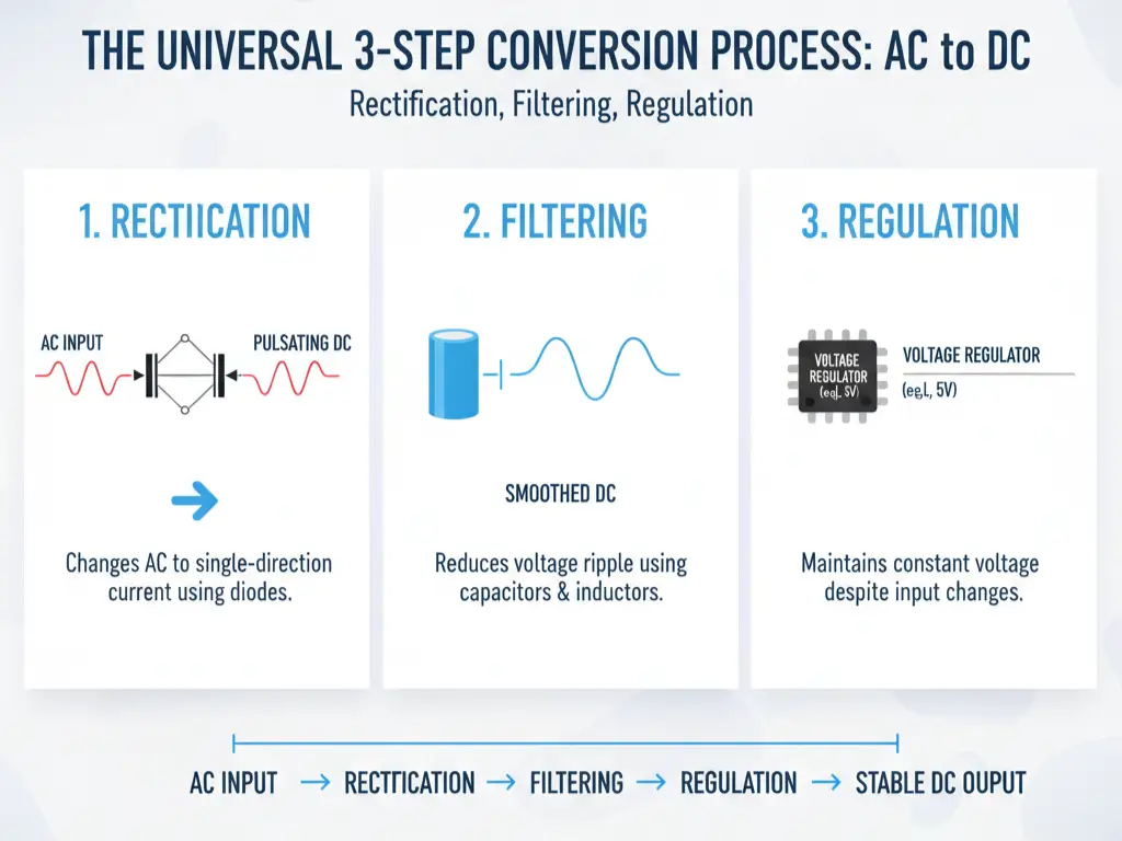
Fundamentally, the process of converting the waving wave of the AC to the flat line of the DC is a three-step refinement process. No matter what particular technology is employed, these are the basic principles of rectification, filtering, and regulation which are universal in taming alternating current into useful dc output.
Rectification: Changing Current’s Direction
The initial and the most important one is rectification. The aim of this step is to push the alternating current that passes in both the positive and negative directions within a current that will pass in a single direction. This is achieved through the use of diodes which are electronic components that serve the purpose of one way valve to electricity.
A full-wave diode bridge rectifier where four diodes are organized is the most prevalent and cost-effective solution. The wiring of this is clever to divert the AC input in such a way that the positive and negative halves of the ac waveform are inverted to only one positive flowing output. This is not AC anymore but it is not pure DC either. It is rather a “pulsating DC” in the form of a succession of positive bumps with a large amplitude of swings.
Filtering: Smoothing the Electrical Flow
The rectifier produces pulsating DC which is still too volatile to be utilized by any electronic component. This would cause the voltage to be repeated to zero in between the peaks, and this would make any device keep on and off. The second process is filtering which is meant to make these bumps smooth out.
This is mostly performed using a huge capacitor and occasionally an inductor coil. A capacitor stores and discharges electrical power. It comes after the rectifier, and it is charged as the voltage rises with each pulse, and discharged gradually as the voltage rises again. This prevents the gaps between the pulses, greatly minimizing the voltage swings (so-called ripple) and transforming the pulsating DC into a much smoother and more constant voltage (typically in VDC).
Regulation: Achieving a Stable Voltage
Whereas filtering greatly smooths the DC, the output voltage remains variable with the changes in the ac mains input or variability in the DC load. In the case of sensitive electronics, this is intolerable. The final step is regulation.
A voltage regulator is an element or circuit that ensures the constant output voltage across these variations. It can be a basic Zener diode, or a complicated integrated circuit (IC), but its task is to convert the filtered DC into a rock-steady, tightly regulated output. As an example, a 5V regulator will produce exactly 5 volts, even with its input changed between 7-12 volts, to provide optimal voltage to the device and make it work perfectly.
Key Components in an AC-to-DC Circuit
While the process is conceptual, its implementation relies on tangible electronic components. For a basic understanding, four key components are central to dc power supply design as described above.
- Transformer: Often the very first component in the chain, a transformer steps the high-voltage AC from the wall outlet (e.g., 120V or 230V) down to a lower, safer AC voltage suitable for the circuit.
- Diode / Bridge Rectifier: Diodes are the one-way gates for current. A bridge rectifier is simply a pre-packaged module containing four diodes arranged for efficient full-wave rectification.
- Capacitor and Coil: These components store and smooth electrical charge, drastically reducing ripple and helping to maintain a steady voltage.
- Voltage Regulator: This IC is the final gatekeeper, ensuring the output remains constant and at the precise level required by the end dc load.
Real-World Implementations and Technologies
It is one thing to know the theory and its components but another to apply them. In practice, these principles are implemented in two main categories of dc power supplies; Linear Power Supplies and Switching Mode Power Supplies.
Linear Power Supply
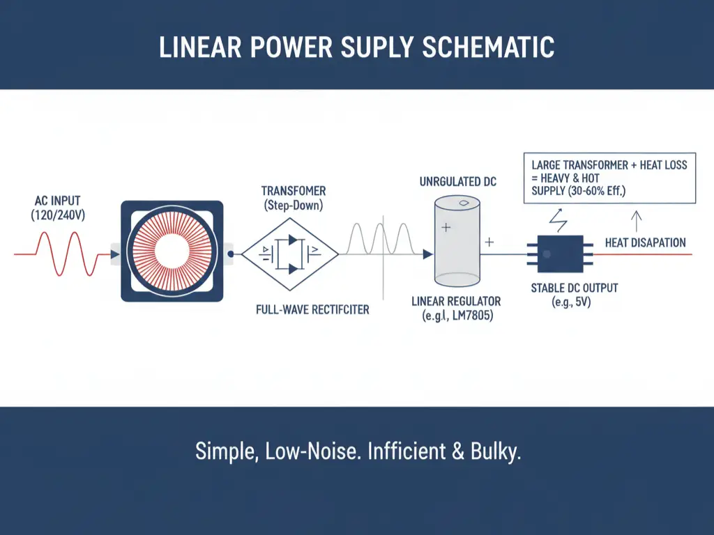
This represents the most straightforward application of the three steps process. It involves a large transformer to reduce the voltage, a rectifier to change it, a large capacitor to filter it and a linear regulator to smooth out the output. Linear supplies are prized because of their simplicity and their very low-noise output, and are mostly used in the sensitive audio and radio business. They however lose the excess voltage in the form of heat (Power = Current × Voltage, not the square root), which makes them inefficient (30 to 60 percent efficiency). The cumulative effect of this wasted energy in association with the large transformer is large, heavy and hot supplies.
Switching Mode Power Supply (SMPS)
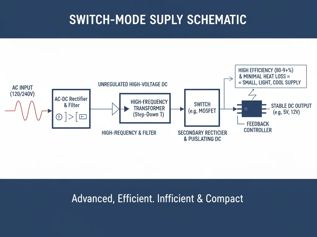
It is much more advanced converter. It corrects the high voltage AC first, and then chops it to thousands of pulses per second by means of a high-frequency switch. These impulses are sent into a high-frequency transformer that is small and lightweight followed by a rectification and a subsequent filtering. The switch is accurately modulated by a feedback controller to enable the SMPS to transform power with a minimum amount of energy wasted. It leads to 80-95+ efficiencies and much smaller, lighter, and cooler power supplies are possible. SMPS units today are standard computer power supplies, phone chargers as well as industrial power source systems.
How to Choose the Right Power Supply
Understanding the two primary technologies naturally leads to the question: which one is right for your application? The choice depends on trade-offs between performance, efficiency, and cost. Below is a diagram summarizing the key differences:
| Feature | Linear Power Supply | Switching Mode Power Supply (SMPS) |
|---|---|---|
| Efficiency | Low (30–60%) | High (80–95%+) |
| Size & Weight | Large and Heavy | Compact and Lightweight |
| Heat Dissipation | High (wastes energy as heat) | Low |
| Complexity | Simple PCB Design | Complex Circuit Design |
| Output Noise | Very Low | Higher (may need filtering for medical devices) |
| Cost | Cheaper at low power | More cost-effective at high power |
| Common Use | Sensitive audio, low-amp circuits | Laptops, chargers, industrial dc converter |
For demanding applications where efficiency, compact size, and reliability are non-negotiable, a high-quality Switching Mode Power Supply (SMPS) is the clear professional choice. When sourcing such critical components, it’s vital to partner with a specialist. OMCH, for instance, offers a wide portfolio of industrial-grade SMPS solutions designed for performance and longevity. Exploring a trusted supplier like www.omch.com can provide the certified and robust power solution your project requires.
Critical Safety Precautions When Handling AC Power
Working with electricity from the ac mains is not the same as working with low-voltage DC from a battery. Mains voltage can cause shocks, surges, or even be lethal. Always follow strict safety protocols:
- Always Disconnect Power before touching any circuit.
- Use an Isolation Transformer when testing live circuits.
- One-Hand Rule to avoid current passing through your chest.
- Use Fuses on the AC input to protect against overload.
- Ensure Proper Grounding to trip breakers safely.
- Avoid Wet Environments, as water conducts electricity.
- Use Insulated Tools rated for mains voltage.
Troubleshooting Common Conversion Problems
Even with good design, issues can arise:
- Problem: No voltage at output
Possible Causes: Blown fuse, broken power cord, faulty PCB connection, or failed regulator. - Problem: Output too low or unstable
Possible Causes: Undersized capacitor, excessive dc load, or input voltage below regulator dropout. - Problem: Overheating
Possible Causes: Excessive current draw (max rating exceeded) or too large input-to-output voltage drop. Heat sinks may be needed.
By understanding these principles, technologies, and safety measures, you are well-equipped to design or troubleshoot dc power supplies that reliably convert ac power source into usable, safe, and efficient stable DC output—powering everything from solar cells to industrial automation.