


Reliability and accuracy are the measures of success in industrial automation. The path between the recognition of a challenge in the production line and the establishment of a powerful control system is a serious one. This process does not start with a component, but with a question: What do we need to do? It is only when the application is defined that we can choose the appropriate hardware, model it in a schematic, and incorporate it into a control circuit.
This comprehensive guide walks you through that essential journey. We will begin with the real-world problem, choose the right sensor technology, apply that decision to the right IEC standard symbol, insert it into a working PLC circuit, and even discuss the more advanced features of the new smart sensors. This is the ultimate guide to the transition between application and automation.
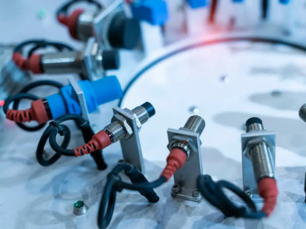
Start with the Application: Choosing the Right Sensor
The physical reality of the application must be known before a single line is drawn on a schematic. The most frequent mistake in system design is choosing a sensor because it is familiar and not because it is appropriate. To prevent this we should start by answering four basic questions about the target and its environment. These are Material, Environment, Distance and Precision, and they make a rational selection framework.
Target Material:
Is the object to be detected metal or non-metal? Is it opaque, transparent or reflective? The underlying sensing technology is mostly determined by the material composition.
Operating Environment:
Will the sensor be exposed to contaminants such as dust, oil or water? Are there extreme temperatures, high vibration, or potential for physical impact? The sensor should be designed and its IP (Ingress Protection) value should correspond to the severity of its environment.
Sensing Distance:
How far apart must the sensor face be the target object (sensing range)? This nominal range may range between several millimeters and several meters.
Precision and Speed:
To what extent must the position of the object be detected? What is the rate at which the target is moving and what is the response time needed by the control system?
These are the considerations that directly inform the choice between the main families of proximity sensors. Although there are many dedicated sensors, the four basic types of sensors can be used to solve most applications: inductive, capacitive, photoelectric, or ultrasonic. To simplify this decision, the table below gives a decision-making matrix.
| Sensor Technology | Ideal Target Material | Key Environmental Considerations | Typical Sensing Range | Primary Strengths |
| Inductive | Ferrous & non-ferrous metals | Highly robust; immune to dust, oil, water. Unaffected by target color | Short (1mm – 60mm) | High durability, high speed, cost-effective for metal detection |
| Capacitive | Any solid or liquid material (metal, plastic, wood, water) | Sensitive to humidity, dust buildup, and temperature changes. | Short (1mm – 40mm) | Versatile material detection, can “see through” thin non-metallic walls |
| Photoelectric | Opaque, reflective, or transparent objects | Performance can be affected by dust, steam, or ambient light. Lens cleaning may be required | Varies (mm to >50m) | Long sensing distances, very high speed, multiple modes (diffuse, retro-reflective, thru-beam) |
| Ultrasonic | Any sound-reflecting material (solid, liquid, powder) | Unaffected by target color or transparency. Can be affected by extreme air turbulence or soft, sound-absorbing materials | Mid to Long (100mm – 8m) | Excellent for detecting clear objects and measuring liquid levels; ignores color |
By methodically working through this table, an engineer can confidently narrow down the optimal technology for the task at hand, ensuring the foundation of the control system is sound.
Case Study: Detecting PET Bottles on a Conveyor
To illustrate this selection process, let’s analyze a common and challenging industrial application: reliably detecting clear Polyethylene Terephthalate (PET) bottles on a high-speed bottling line conveyor.
The Problem:
The goal is to obtain a consistent count of bottles and to trigger downstream actions like filling or capping. The bottles are transparent, move quickly, and may have slight variations in position on the conveyor.
The Analysis & Elimination Process:
We begin by applying our four key factors:
- Material: The target is PET plastic, a non-metal. This immediately eliminates inductive sensors, which function by detecting changes in an electromagnetic field caused by metallic objects.
- Environment: The environment is relatively clean but may involve moisture or washdowns. Speed is a critical factor.
- Distance: The sensor will be mounted close to the conveyor, with a sensing distance of approximately 100-300mm.
- Precision: We need a reliable on/off signal for each bottle.
Since the inductive sensors are not an option, we look at the other possibilities. A capacitive sensor would technically be able to sense the plastic and the liquid within, but its limited sensing distance and possible sensitivity to ambient humidity would be a less dependable option in a high-velocity, possibly wet, environment. An ultrasonic sensor might be effective, because it is not sensitive to transparency. But it tends to be slower than photoelectric ones, because of the speed of sound wave propagation, and is not well suited to high-speed applications.
The logical result of this process is photoelectric sensors. However, even in this family, one has to make a decision. A typical diffuse photoelectric sensor, which directly reflects the light off the target, would probably fail. Most of the light would be scattered or transmitted through the clear, curved surface of the PET bottle, and an unreliable signal would be obtained.
The Optimal Solution:
A retro-reflective photoelectric sensor is the strongest solution. This setup employs a sensor and a discrete reflector. The sensor produces a beam of light which is reflected back to the sensor. As a PET bottle passes between them, it interrupts this stable beam. The minimal difference in the refraction and reflection of light due to the material and the curved surface of the bottle is sufficient to interrupt the beam path, giving a clean high-speed trigger. To achieve the highest reliability in sensing very clear objects, a model with a polarizing filter is employed to reject the reflection of shiny surfaces other than the specialized reflector.
This methodical approach, moving from problem to technology, ensures the selection of a sensor that is not just functional, but optimized for the specific challenges of the application.
From Sensor to Symbol: Correct Schematic Representation

After the retro-reflective photoelectric sensor is chosen, the second step is to model it correctly on an electrical schematic. It is not just a drawing exercise; the schematic symbol is an exact bit of technical communication that tells anyone who is building, troubleshooting or maintaining the system. These symbols have the universal language in the international standard IEC 60617.
In the case of our selected photoelectric sensor, the simplest symbol is a square, which is the device enclosure. Internally, graphics refer to its role. Here, a light emitter and a light receiver are represented by symbols, and an icon that it is a retro-reflective type.
Nevertheless, the symbol should not only represent the sensing technology. Two important electrical configurations have to be specified: the output type (PNP vs. NPN) and the default logic state (NO vs. NC).
PNP vs. NPN: This defines how the sensor’s output switches the electrical load.
- PNP (Sourcing): The sensor’s output switches the Positive (+) voltage to the load (e.g., a PLC input). When activated, the output connects the load to the +24VDC supply. This is the most common standard in Europe and North America.
- NPN (Sinking): The sensor’s output switches the Negative (-) or 0V connection to the load. When activated, the output connects the load to the 0V (GND) rail. This is more common in Asia.
NO (Normally Open) vs. NC (Normally Closed): This defines the sensor’s output state when it is not detecting a target.
- Normally Open (NO): The output switch is open by default. When the sensor detects the PET bottle, the switch closes, and a signal is sent. This is ideal for presence detection tasks.
- Normally Closed (NC): The output switch is closed by default, providing a continuous signal. When the sensor detects the bottle, the switch opens, and the signal is interrupted. This can be useful for fail-safe applications, as a broken wire would produce the same state as a detected object.
In our PET bottle application we have to count bottles as they come. Thus, a Normally Open (NO) is suitable. A PNP output would be a typical option assuming the control system is a modern PLC in North America.
So, we have settled on a Retro-Reflective Photoelectric Sensor, PNP output, Normally Open (NO) logic. Small notations will be added to the schematic symbol to represent this complete specification, so that there will be no ambiguity whatsoever on the circuit diagram.
Common Proximity Sensor Symbols and Their Meanings
To ensure clarity in schematic design and effective communication across engineering teams, standardized symbols are used to represent different types of proximity sensors and relays. These symbols, governed by the IEC 60617 standard, visually encode the function and configuration of a sensor without ambiguity. Below is a breakdown of the most commonly used proximity sensor symbols:
- Inductive Proximity Sensor
- Symbol: A square (representing the device housing) with a coil or loop inside.
- Use: Detects metallic objects using electromagnetic fields.
- Note: Often labeled with “Ind” or includes an inductor graphic.
- Capacitive Proximity Sensor
- Symbol: A square with two parallel lines (representing capacitor plates) or an open-ended rectangle.
- Use: Detects both metallic and non-metallic objects. Please include a screenshot if you are requesting further details.
- Note: Sometimes includes a dotted line or material identifier inside the square.
- Photoelectric Sensor
- Symbol: A square with an arrow (light beam) directed at a target.
- Variants:
- Diffuse: Both emitter and receiver in one unit.
- Retro-reflective: Arrow reflects back from a symbolized reflector.
- Through-beam: Separate emitter and receiver symbols connected by a line or arrow.
- Use: Detects presence through light interruption.
- Ultrasonic Sensor
- Symbol: A square with curved lines (representing sound waves) emitted from one side.
- Use: Suitable for clear or transparent targets and longer-range detection.
- Sensor Output Type Notations (PNP/NPN)
- PNP (Sourcing): Often indicated with an upward-pointing triangle or labeled “+”.
- NPN (Sinking): Often indicated with a downward-pointing triangle or labeled “-“.
- Tip: These notations are added near the symbol or documented in wiring legends.
- Logic State (NO/NC)
- Normally Open (NO): The default state shows an open contact; it closes when activated.
- Normally Closed (NC): Shows a closed contact; opens when the sensor is triggered.
- Representation: Typically shown in auxiliary diagrams, contact blocks, or annotations near the sensor symbol.

Summary Table
| Sensor Type | Symbol Characteristics | Typical Notation |
| Inductive | Square with coil symbol | “Ind” or inductor |
| Capacitive | Square with parallel lines | “Cap” or plates |
| Photoelectric | Arrows/light beams + target | Diffuse / Retro / Thru-beam |
| Ultrasonic | Square with curved sound waves | “US” or wave icon |
| Output Type | Triangle (up = PNP, down = NPN) | “+” / “-“ |
| Logic State | Contact symbols (open/closed) | NO / NC |
Understanding and correctly applying these symbols ensures that system schematics are intuitive, internationally understood, and ready for troubleshooting or expansion.
Wiring to a PLC: Drawing the Control Circuit
The schematic symbol is an abstract representation; its true purpose is to guide the physical wiring of the control circuit. Integrating our PNP, NO photoelectric sensor with a Programmable Logic Controller (PLC) input module is a fundamental task in automation. A typical 3-wire DC sensor requires three connections: power, common, and signal.
The circuit consists of three main components:
- The 24VDC Power Supply: Provides the operating voltage for the sensor and the PLC. It has a positive (+) terminal and a 0V (common) terminal.
- The Proximity Sensor: Has three wires. For our PNP sensor, these are typically color-coded:
- Brown: +24VDC (Power In)
- Blue: 0V (Common)
- Black: Signal Output
- The PLCInput Module: This module has multiple input terminals and a common terminal. It reads the voltage state of the signal wire to determine if the sensor is “on” or “off.”
Wiring a PNP (Sourcing) Sensor:
In a PNP configuration, the sensor “sources” or provides a positive voltage to the PLC input when it detects the target. The wiring is as follows:
- The sensor’s Brown wire connects to the +24VDC terminal of the power supply.
- The sensor’s Blue wire connects to the 0V terminal of the power supply.
- The sensor’s Black signal wire connects to a specific Input Terminal on the PLC (e.g., I0.0).
- The PLC input module’s Common terminal is connected to the 0V rail of the power supply to complete the circuit.
Diagrammatic Representation of Current Flow (PNP):
+24VDC ----------------------> Brown Wire (Sensor)
                             |
                             V
                          [Sensor]
                             |
PLC Input (I0.0) <-------- Black Wire (Sensor)

0V -----------------------> Blue Wire (Sensor)
                             |
                             V
                          [PLC Common]
When the PET bottle is detected, the internal switch in the PNP sensor connects the Brown (+24V) wire to the Black (Signal) wire. This sends a +24VDC signal to the PLC input terminal, which the PLC’s processor registers as a logical “1” or “high” state.
Contrast with NPN (Sinking) Wiring:
For clarity, an NPN sensor operates in the opposite manner. It “sinks” current from the PLC input to ground. The PLC input’s common would be tied to +24VDC, and the sensor’s output would pull the input terminal down to 0V when activated. Correctly interpreting the PNP/NPN designation on the schematic is absolutely critical for functional wiring and preventing damage to components.

The Smart System: Introducing IO-Link Sensors
Over decades, the output of a proximity switch has always been a binary signal: ON or OFF. This works well in simple control tasks but the current manufacturing process requires additional data, flexibility and intelligence across all levels of the factory floor. This is the domain of IO-Link.
IO-Link is not a second industrial bus network such as EtherNet/IP or Profinet. A standardized point-to-point communication protocol (IEC 61131-9) enables a typical 3-wire sensor cable to perform far more than a simple switch signal. It establishes an electronic communication interface between the sensor and an IO-Link Master module, which subsequently interprets the data to the main PLC or control system.
The value this technology adds to our PET bottle application is significant:
- Process Data: The IO-Link sensor is capable of sending more detailed data than just an ON/OFF. As an example, it may give an analog value of the signal strength, so that the system can know whether the sensor lens is gradually getting dirty before it is too late.
- Diagnostics: The sensor is able to proactively report its health and status. It is capable of providing warnings of such critical faults as short circuit, overheating, or internal faults. This allows predictive maintenance, whereby technicians can solve problems before they lead to unplanned downtime.
- Parameterization: Remote and on-the-fly sensor settings can be modified at the PLC. When the production line changes to a slightly different bottle type that needs a new sensitivity level, the change can be performed immediately in software without the technician physically having to touch the sensor and use a tiny screwdriver to change the sensitivity level. This is essential in applications that are frequently changed.
An IO-Link sensor is not depicted in a conventional circuit-level symbol in a system architecture diagram. Rather, it is depicted as a labeled block that is attached to an IO-Link Master. This master device is a gateway, which aggregates data of several IO-Link sensors and transmits it via a fieldbus network to the central controller.
When we upgrade our retro-reflective sensor to an IO-Link-enabled device, we turn it into a smart data source, which gives us the visibility and control needed in Industry 4.0 projects and results in a more resilient, efficient and flexible automation system.
Conclusion: The Blueprint for Reliability
The route between a real-world problem, such as the detection of a transparent bottle, and a completely documented control circuit is a fundamental engineering science. It shows that symbols on a schematic are not random drawings; they are the succinct and potent result of an exacting process of analysis and choice.
When you begin with the application at all times, you are assured that the technology that you have selected is purpose fit. Using a case study, you turn abstract requirements into a physical solution. That solution can be codified to be understood by all by understanding the language of symbols and wiring standards such as PNP/NPN. Lastly, when you look forward to technology such as IO-Link you build systems that are not only operational today but also smart and flexible to meet the challenges of tomorrow. It is this systematic, end-to-end approach that is the roadmap to designing automation systems that are resilient, maintainable and genuinely reliable.
OMCH: Your Partner in Industrial Automation

Theory and practice are discussed, and the right selection of components is crucial to the success of your project. How well a well-designed schematic will translate to a reliable, functioning system is determined by the quality and availability of the hardware you specify. As important as the design is, is a strong supply chain and professional technical support.
We do not only provide our distribution partners with a full line of proximity sensors, starting with simple inductive units, to sophisticated photoelectric models with IO-Link capability, but also with technical expertise at OMCH (https://www.omch.com/). We know that our partners are not simply relocating boxes, they are resolving complicated automation problems to their customers.
You may be an equipment manufacturer upgrading a production line or a system integrator designing a new control system, we have a one-stop source of reliable automation parts. We are dedicated to making your solutions effective and efficient with components that offer performance and a partnership that offers confidence.


