


Electrical relays are one of the most basic, but also one of the most versatile components in the huge realm of electronics and electrical engineering. Doug Brinton Can Stats To the core, they are s simple, but clever, means of controlling a high-power electrical load with a low-power electrical signal, or light signal, which is how the backbone of all automation and control systems are constructed everywhere. The relays are the unsung heroes, which enable the industrial machinery that drives our world as well as the daily convenience of automotive electronics. The term relay though covers a broad family of products–various kinds of relays, each distinguished by kind of switching device, kind of terminals, and other parameters. The comprehension of these distinctions is not simply in the academic setting. It is essential when formulating safe, practiced, and established electrical circuits. This guide is a walk through the logic understanding principles of the relay operation, to the application steps of relays where you can select the most appropriate relay to your application in a very confidence manner.
What Is a Relay and How Does It Work?
A relay can simply be defined as an electronic relay or rather an electromechanical induction, which functions as a switch that is operated electrically. It is mainly used to electrically isolate a control input signal to a load circuit. The relay is driven by the power source: typically low voltage and current draw (e.g. 5V fed by a microcontroller). When this is done the switch in the relay either physically or electronically is closed, completes an independent, high-power electrical circuit (e.g. a 240V AC supply to a motor). The most important feature of this separation is that it isolates sensitive control electronics to the high voltage, back emf and electrical noise of the power circuit.
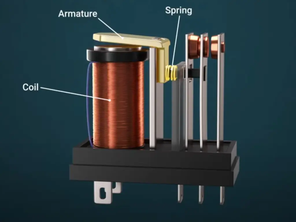
The best-known one is the electromechanical relay (emr relays). Its mode of operation gives a pure example of electromagnetic induction. Within an EMR a small loop of wire behaves as an electromagnet. Connected to this coil, by the control circuit with a voltage, is a magnetic force. This is a magnetic attraction that pulls towards a movable armature which is a minor lever. When the armature rotates, it forces a pair of physical contacts together closing the switch with which an electrical current may pass through the electrical load. Once the control voltage is off the armature, the magnetic field collapses and a spring or permanent magnet drives the armature back to its regular state and the pose of its contacts reverses, again breaking the circuit. This is the fundamental, basic and strong relay mechanism on which we all can base all others of different types of relay.
Key Relay Terminology You Must Know
Above discussing the various types of relays, it is important to familiarize with the common jargon applied in describing the characteristics of relays and as well as its operations. The first step to getting it right is mastering this vocabulary, so that it is easier to read through datasheets, and pick the right component.
Pole & Throw
This refers to the intwined structure of the switch of the relay.
- Pole is the connection of a relay and is the number of independent circuits controlled by the relay. There is one circuit controlled by a Single Pole (SPST relay). A Double Pole (DP) relay has two once independent circuits on the same relay. Throw is referred to as the amount of positions that the pole can be attached to.
- A Single Throw (ST) relay is basic ON/OFF with only one other connection made to the pole. A Double Throw (spdt relays) may change the pole to two other different contacts and thus redirect the current flow. Common AR forms are SPST (Single Pole, Single Throw), SPDT (Single Pole, Double Throw) and DPDT (Double Pole, Double Throw).
Contact Form (NO, NC)
This defines the contact position and default state of the relay’s contacts when the coil is not energized.
- Normally Open (NO): The switch contact is open in normal position leaving the circuit incomplete. When power is applied to the coil, that closes the contact and the circuit is complete.
- Normally Closed (NC): The switch contact closes as it rests in the normal position and the circuit is complete. When power is applied to the coil the contact is opened and the circuit is broken.
- A Single Pole Double Throw (spdt relay) will contain one common terminal, one normally open (NO) on and one normally closed (NC) on.
Coil Voltage & Contact Rating
These are two of the most critical electrical specifications.
- Coil Voltage: This is the amount of voltage needed in the control circuit that will be assured when the coil in the relay is energized. The rating should be at the same voltage of the input of your control (e.g. 5V, 12V, 24V DC as a signal).
- Contact Rating: This indicates the highest voltage rating, current rating that relay physical contacts can safely accommodate. It is normally stated in amps (A) at a given voltage and type of electrical load served (e.g. 10A at 250V AC). Reading above the contact rating may cause contact resistance to rise, generate some sort of heat, and fail.
Major Types of Relays by Construction
Although all the relays serve some switching purpose, the manner in which they have been structured inside them is the deciding factor in defining their performance parameters, low current requirement, and their applicability to various electrical networks. Learning about the five significant types will help in making an effective decision.
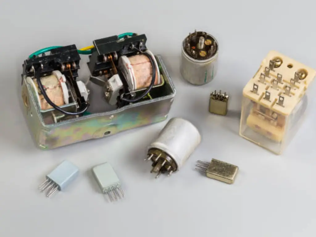
Electromagnetic Relays (EMRs)
The most traditional and widely well-known ones are Electromagnetic Relays. They function by the law of magnetic force as explained above that physically move physical contacts. Opened they have a real air gap between contacts, guaranteeing very good electrical isolation. This makes them insensitive to transient on transmission lines and breakers. They are able to switch AC and DC electricity, tend to be cheap, but have the drawback that they are only as fast as the mechanical switching system, and that they have a finite lifetime since the contact position can wear out.
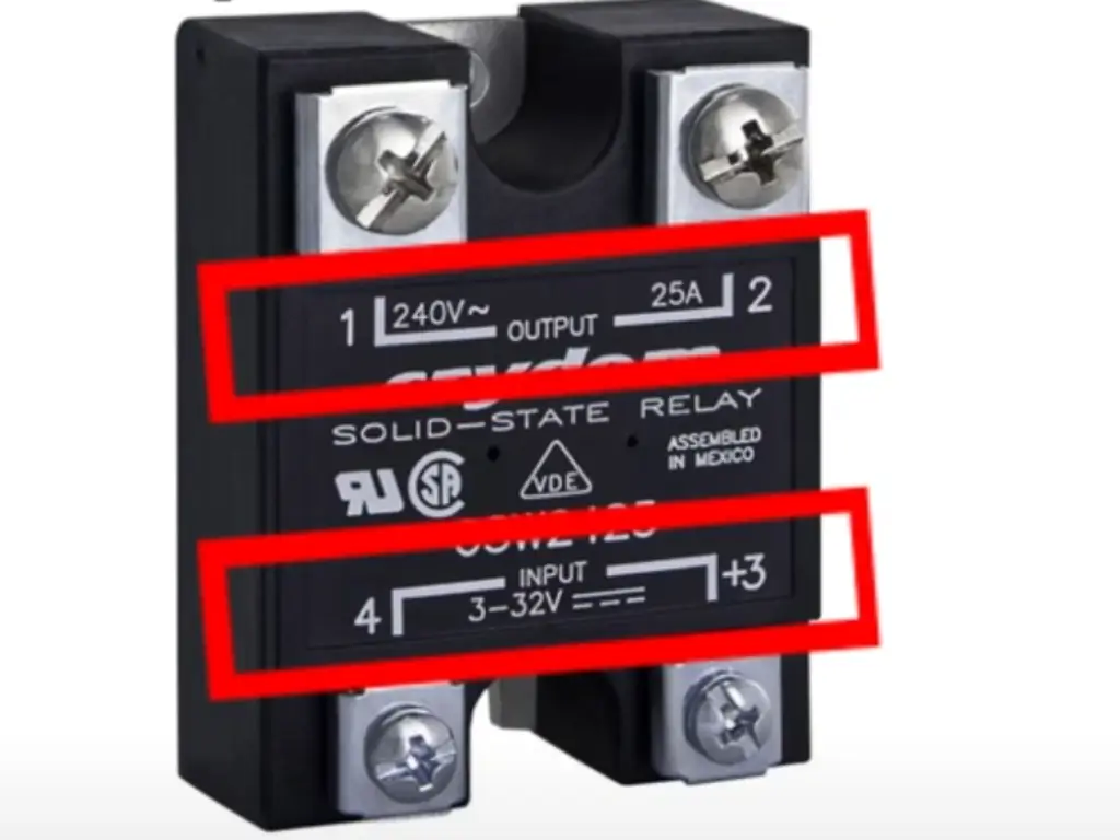
Solid-State Relays (SSRs)
A solid state relay is a more modern switching device, none of which has actual contacts. Rather than a single coil they utilise semiconductors to alternate the current flow, with the input signal being coupled via an optocoupler as a form of isolation. SSRs consume little power, they do not generate any noise, they are quick as well as tough. Nevertheless, they possess their own contact resistance, might need cooling due to surrounding temperature and are pricier.
Thermal Overload Relays
The Thermal Overload Relays are protection relay devices which protect motors by protecting them against over current. They work on an electrical current that heats a piece of bimetallic strip. When electrical load is excessive, the outcome kind of heat causes the strip to bend, which alters the place of contact and the removing of the load. Channelling Their time delay relay operating characteristics enable them to pass short inrush currents without tripping unnecessarily.
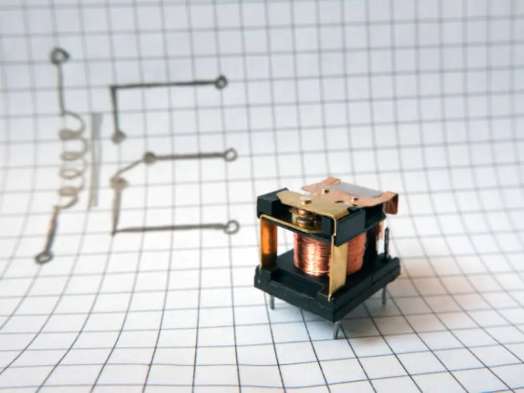
Reed Relays
A reed relay is a special form of relay in which contacts are made of two ferromagnetic reed enclosed in glass. They are placed within a coil which on energization also pulls the reeds together magnetically. This is hermetically weatherproofed against environmental conditions such as dirt and water. Fast and low power consumption applications where low current is needed they are small, fast, reliable but have low current rating.
Hybrid Relays
Hybrid Relays can be used to contain an electronic relay device and an EMR in a single unit, in which an SSR can be utilised to perform short term switching then leave the EMR to maintain the electrical current. This minimizes back emf and arcing when switching as well as effective current flow and low energy consumption.
Different Types of Relay: A Comparison
Picking between the two types needs a good comprehension of the trade-offs. The table below shows the direct comparison of the most popular relay types according to the most important performance indicators.
| Feature | Electromagnetic Relay (EMR) | Solid-State Relay (SSR) | Reed Relay |
| Switching Speed | Slow (5–15 ms) | Very Fast (<1 ms) | Fast (0.5–2 ms) |
| Lifespan | Limited (mechanical wear) | Very Long (no moving parts) | Long (sealed contacts) |
| Cost | Low | High | Moderate |
| Electrical Noise | High (arcing & EMI) | Very Low | Very Low |
| Size | Bulky | Compact (may need heat sink) | Very Compact |
| Power Consumption | Higher | Low | Very Low |
| Vibration/Shock | Susceptible | Highly Resistant | Moderately Resistant |
| Best Use Case | General high-power AC/DC switching | High-frequency silent switching | Low-level signal switching |
And repeating in summary, you will want to use an SSR in preference even to cost, when your application requires low power loss, switching speed and long life. EMRs are cost-effective in general-purpose high-power. A reed switch is good in sensitive equipment where space is at a premium.
How to Choose the Right Relay: A 4-Step Guide
Having a good background behind the type of relay and their paramaters, you may now rely on the systematic procedure of choosing an ideal component.
Step1: Define Your Load (AC/DC, Voltage, Current)
Describe the electrical load that you want to switch. Find out whether the load is DC or AC, its voltage rating and its current rating. A relay should always be of a rating comfortly exceeding those of the load, with a safe margin, especially when the load is inductive transmission lines or circuit breakers.
Step2: Determine Your Control Signal
Examine your input on control. What is the availability of power source voltage to energize relay? Make sure the electrical current available to energize relay coil or semiconductor is adequate at your control circuit.
Step3: Consider Switching Frequency and Lifespan
What is the frequency of switching of the relay? A solid state design or latching relay can be more well suited to continuous or frequent operation. Where the switching need not be performed frequently an emr relay can be used.
Step4: Assess Environmental and Physical Constraints
Think in terms of ambient temperature, noise, vibration, time delay relay needs and board space. Select the type that satisfies these needs on the environment and mechanical grounds without a lot of contact resistance or generation of much type of heat.
Practical Application and Wiring Diagram
Let’s put this into practice with a hobby project: Controlling a Lamp with an Arduino and a Relay Module.
Control Circuit:
- Module VCC → Arduino 5V
- Module GND → Arduino GND
- Module IN → Arduino Digital Pin (e.g., Pin 7)
Power Circuit:
- Cut the live AC wire.
- One end → relay COM terminal.
- Other end → relay NO terminal.
When the Arduino sends a HIGH input signal, it energizes the relay, closing the physical contacts and completing the load circuit, turning the lamp on. When the signal goes LOW, the relay returns to its normal position, opening the circuit.
Sourcing Quality Relays for Your Application
When you have established your needs, then its time to find genuine high quality parts. Look at other attributes other than price that includes manufacturer reputation, genuine parts, and elaborated datasheets. When it comes to industrial use where regular quality and wide selection are desired, vendors, such as OMCH at omch.com, are priceless. General-purpose EMRs as well as advanced, solid state, relay, latching relays and protection relays require a dedicated supplier that can be depended upon to ensure their performance.
Final Thought
To sum up, the relay, as various forms of it, stands out as the example of great engineering aesthetics. Getting familiar with its principles, learning its terminology and being aware of the unique benefits of each type, you make it a great tool in design. Having a systematic approach to the selection of a part guarantees that not only do you end up with a functioning part but also with the best performing, safe, and long-lasting design of your product. It does not matter if you are in the business of making complex electrical circuits in an industrial industry or you are a hobbyist doing some experiments, the correct relay is still the foundation of a successful project.


