


Beyond the Click: What Is a Solid State Relay?
The distinctive sound of a conventional relay is well known to the field of electronics and industrial control use with its tell-tale click-clack. Physically it is the acoustic trace of an electromechanical switch (EMR) transforming a circuit, closing a circuit and turning off a load.
This has been the norm of the past couple of decades. However what would be the case when the switching can be done silently, immediately and with orders of magnitudes greater lifetime? That is the territory of the Solid State Relay (SSR).
Fundamentally, a Solid State Relay is an electronic switching circuit, which executes the same task similar to an electromechanical relay albeit with no moving parts. The solid-state is a category term. It is the field of physics and electronics describing the behavior of the solid state of transmitted current in the semiconductor materials. As opposed to the physical contacts being forced together by the force of an electromagnet creating a magnetic field, through the inherent electrical characteristics of a semiconductor substance (like silicon) an SSR switches a load circuit on and off.
The lack of moving parts is the one and only most distinguishing feature of an SSR and the reason behind its major benefits. No metalic contacts are there to arc, pit, or wear out, no coils to burn out, and no springs to lost their tension. This is entirely an electronic control with a low power electrical input first-operating signal which activates a high-current output circuit. This is the inherent architecture divergence which does not only render the SSR a silent substitute, it actually provides a better technologically solution to a wide range of modern applications requiring precision, reliability and longevity. This tutorial will lift the hood on these Machines, their fundamental distinction to older relays, and how to make a wise decision to use the proper kind.
Inside the SSR: How It Switches Electronically
In order to be able to appreciate what capabilities a Solid State Relay can offer, the internal structure has to be understood first. A common SSR has three main functional blocks, the input circuit, the isolation (or coupling) circuit, and the output switching circuit, although the block diagram may look different. Both have a specific and very important role in the functioning of the device.
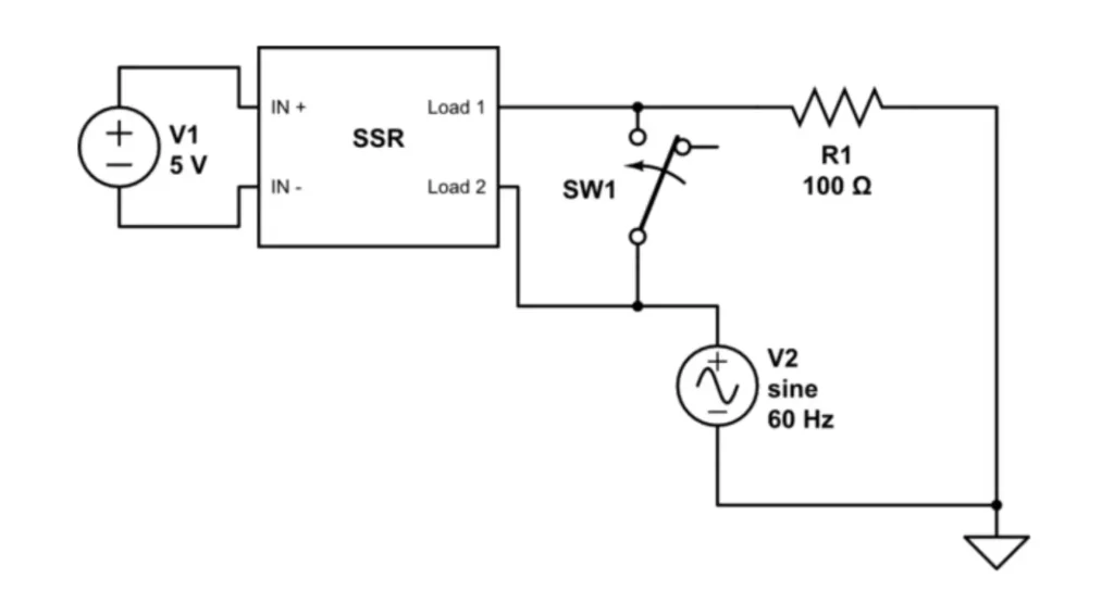
- The Input Circuit: It will be the point of entry where the logic of the system (e.g., a PLC or a microcontroller or a sensor) would provide the control signal. This control signal is a low power as which many standard models have a range of 3-32V DC. This is often known as the DC input. Main tasks of the input circuit are to condition this signal and drive the isolation stage. It may incorporate a status LED and a current-limiting resistor: the status LED mostly lit when the control voltage is applied to give a convenient visual feedback of the status of the relay.
- The Isolation (Coupling) Circuit: This is probably the most important aspect to the design of an SSR. It serves to provide an electric isolation–a dielectric gap–between the low-voltage control logic and the high-voltage electrical load. Such galvanic isolation is considered part of safety because it ensures that the the high voltage of the load will never appear on the sensitive control electronics or the human operator. Opto-isolator (another name is optocoupler or photocoupler) is the most popular solution to do so. An opto-isolator is composed of an LED on the input side and a photosensitive semiconductor (such as a phototransistor or photodiode) on the output side all packaged in one opaque package. The LED is powered by the input circuit when the control signal comes and produces infrared light between the gap created inside. The photosensor senses this light triggering the output switching circuit. Since the transfer medium is a beam of light, the electrical path is non-existent between the two conductors, there is, therefore, very high isolation commonly measured in thousands of volts.
- The Output Switching Circuit: The heavy-lifter of the SSR. It is turned on by isolation circuit and it turns on the high-power load. Depending on the category of load which the component is meant to switch (AC or DC) the parts in the output circuit are selected.
- In the case of AC loads, the most popular switching device is a Thyristor, in the form of a Silicon Controlled Rectifier (SCR) or better known by the term a TRIAC (Triode for Alternating Current). TRIAC consists of two SCRs fastened together in inverse-parallel, hence, it is able to carry current in both the directions at the same time across an AC sine wave. Even the more advanced AC SSRs switch half way through a sine wave to permit more gradual current transitions.
- DC loads that are usually switched with a power transistor, e.g. Metal-Oxide-Semiconductor Field-Effect Transistor (MOSFET) or Insulated-Gate Bipolar Transistor (IGBT), these three components being also known as switching transistors. Some smaller (and cheaper), DC SSRs, only have a single MOSFET, which provides accurate switching with minimal losses. Direct current switches These switches are also used as very fast, efficient high-current control devices, with good control over current output.
By integrating these three stages, the SSR provides a robust, safe, and highly efficient method for digital logic to control significant electrical power without any physical contact.
Solid State vs. Mechanical Relay: Key Differences
Selecting between Solid State Relay (SSR) and conventional Electromechanical Relay (EMR) is an important design process. Even though they have the same general purpose, they have the difference between their worlds in terms of performance. A side-by-side comparison can show the exact benefit and trade off of each of the technologies.
| Feature | Solid State Relay (SSR) | Electromechanical Relay (EMR) |
| Lifespan | Extremely Long (billions of cycles) | Limited (100k – 1M cycles) |
| Switching Speed | Very Fast (microseconds) | Slow (5-15 milliseconds) |
| Operating Noise | Silent | Audible “clicking” sound |
| EMI/RFI | Very Low (no arcing) | High (produces significant arc) |
| Vibration/Shock | Highly Resistant | Susceptible to failure |
| Control Power | Very Low (milliwatts) | Higher (requires coil current) |
| On-State Resistance | Small Voltage Drop | Near-zero contact resistance |
| Off-State Leakage | Small Leakage Current | True open circuit (no leakage) |
| Heat Generation | Generates heat, needs heatsink | Minimal heat from contacts |
| Cost | Higher initial cost | Lower initial cost |
Let’s delve deeper into these critical distinctions:
- Longevity and Reliability: Over all the most important benefit of SSR. Since it contains no moving parts then it does not have wear and tear. Contacts physically wear out in an EMR due to arcing and impact with each action as a result of which they have a limited lifetime. When used within their specification, SSRs have a life up to 100 times longer, and so are more suitable to be used where frequent switching is involved.
- Speed and Performance: Unlike the physical inertia that constrains the EMRs, SSRs can activate and deactivate in microseconds as opposed to 5 to 15 milliseconds. Such a high speed is essential in applications such as precise temperature control (e.g., a temperature controller) or a high speed automation in which fast cycling periods are required.
- Noise and Interference: The fact that an SSR does not generate noise can be an obvious advantage in areas of high noise-sensitivity such as in medical centers or intelligent buildings. More importantly, the lack of contact arcing also implies that SSRs produce very small amount of electromagnetic interference (EMI) and radio-frequency interference (RFI). EMR produces strong electrical noise and this kind of thing can be referred to as the spark that EMR makes when it touches certain sensitive electronics. This is essential where electro-sensitive equipment has to be handled.
- Durability: SSRs are enclosed in epoxy which makes them very durable to shock and vibration damage. EMR, with its finely adjusted mechanical parts, will self-destruct or do chatter, when presented with identical environmental conditions, e.g., in industrial ventilation systems.
- Trade-Offs: The SSRs are not an ideal switch. The output devices semiconductor display a tiny internal resistance leading to a tiny voltage drop when switched on. This loss gives into heat that is proportional to the current flow through the load (P = Vdrop Iload). As a result, SSRs sometimes need a heat sink to dispose this thermal energy, to avoid overheating. More in comparison, EMR closed metal contacts are nearly zero, and they form minimal heat. Moreover, the leakage current with an off SSR can be very low, never being actually zero, whereas the off an EMR can be regarded as an air gap with effectively infinite resistance.

AC vs. DC: Understanding Different SSR Types
The first factor in the choice of a SSR is the type of load which will be operated. Solid State Relays have the specific design to either AC or DC and the internal current output circuit design is in essence different.
AC Solid State Relays
The most popular type are AC SSRs which are intended to switch mains voltages (e.g. 120V, 240V, 480V AC). As stated they either employ a TRIAC or a dual back-to-back SCR as the output switch. Much attention of the many AC SSRs is given to zero-crossing detection. A zero-crossing relay has an internal circuitry which monitors when the AC sine wave crosses the zero volts point before switching the output ON or off.
- Benefit of Zero-Crossing: Zero-Crossing advantage Switching a heavy AC load at the crest of its sine-voltage wave can produce an inrush of tremendous current with high levels of RFI. This means that by simply switching at zero-volt point, it is much smoother. That effectively relieves a lot of abuse on the load (particularly on incandescent lamps and capacitive loads) and electrical noise generated is kept to a minimum. It is generally the default behaviour of most resistive loads such as heater and lamps. Conversely certain SSRs allow switching in the middle of a sine wave peak when used with inductive loads where this is advantageous.
DC Solid State Relays
DC SSRs are optimised to switch direct current loads, which occur mainly in battery powered systems, automobiles and control of dc motors or solenoids. They employ switching elements, such as power transistors (such as MOSFETs or IGBTs). When compared to a TRIAC which would turn off itself at the AC zero-cross, a MOSFET is more of clear and instant solenoid. It gets turned on when a signal is applied at the control signal and the turn off is instantaneous once the signal is withdrawn. This can support very high frequency switching and pulse-width modulation (PWM) of DC loads to PW the speed or brightness. Back emf is also a type of reverse voltage that when not protected can destroy the relay when controlling motors.
Other Key Classifications
Beyond the AC/DC distinction, SSRs are also categorized by:
Switching Type:
- Zero-Crossing: For most common AC applications (resistive loads).
- Random Turn-On (or Instantaneous): These AC relays switch on immediately that a control signal is provided, irrespective of the location of the AC waveform. They are necessary to govern inductive loads (such as motors and transformers), and to use where fine phase control is desirable.
- Peak Turn-On: These AC relays turn on at the peak of the AC’sine wave and as such, are very well suited where loads are highly inductive and where inrush current must be controlled.
Mounting Style:
- Panel Mount: These are more heavy so called units and are placed either on a chassis or a heat sink. They are applied in switching high currents (commonly 10A to 100A+), which is often quoted in amperes.
- PCB Mount: These may be smaller, frequently in a “Single In-line Package” (SIP) or “Dual In-line Package” (DIP) format and can be soldered directly to a printed circuit board in order to switch lower currents using smaller relay terminals.
When to Use an SSR: Advantages and Applications

The Solid State Relay unique features make them excellent in a broad spectrum of applications where the electromechanical relays are not applicable. The necessity to be highly reliable and fast switching, low noise, and precise are the driving factor in the use of an SSR.
Here are some of the most common applications:
- Industrial Heating and Temperature Control: This is traditional SSR application. Exact temperature should be controlled in industrial ovens, plastic molding machines, and semiconductors processing. SSRs enable a PID controller to switch a heating element on or off frequently enough at times (a method known as time-proportioning) to enable an incredibly stable control of the heating element, being impossible to control with a slow-wearing EMR.
- Lighting Control: SSRs are used to control large scale theatrical, and architectural lighting systems where silent, sonority is required. They are ideal to deal with the high inrush current of incandescent or LED lamps and the rapid switching ability makes them ideal to smaller buildings, and flickerless effect suitable to dimming.
- Medical Equipment: In patient facing medical equipment, silence is essential to comfort and reassurance. Moreover, SSRs are highly reliable (much more than relays), and produce little or no EMI, which is vital in the safe operation of such sensitive equipment as dialysis machines or incubators without derailing the work of other sensitive monitoring equipment.
- Industrial Automation (PLC Outputs): During automation of factories, Programmable Logic Controllers (PLCs) may require to control such mechanisms and devices as motors, solenoids, valves and actuators. By having SSRs as the interface between the low-voltage PLC outputs and the high power machinery, it will guarantee a long maintenance-free life in a high-vibration electrically noisy factory environment.
- Smart Homes and Appliances: Appliances that are smart and controlled of the house are indeed perfect with PCB-mount SSRs due to their silent nature of operation and size, which will not cause that annoying audible sound of a mechanical relay.
How to Select the Right SSR for Your Project
Selecting the right SSR is not just a case of impedance matching voltage and current; it must be carefully planned as a way to be safe, reliable and to work well. Failure to set one of the fundamental parameters may result in relay being prematurely destroyed or the control load. These are the key points to take into account:
- Load Type (AC or DC): The first and principal decision is to define which type of load should be used. You have to match relay to the load as explained previously. Application of a DC SSR on an AC load or the two will not work.
- Operating Voltage: When using 3-phase power, choose an SSR with a numerically high maximum operating voltage rating to give a safety margin over the nominal power system voltage against line surges, transients and semiconductor -heat transfer electrode current leakage. A typical and safe SSR selection would be a 480V or 600V rated SSR with a 240 V AC line.
- Maximum Load Current and Derating: The current rating applies to an ambient temperature (e.g. 25 o C). But when the temperature is high, the current carrying capacity of the SSR reduces. This is called derating. You need to download the datasheet of the manufacturer of the relays and find the curve of derating and choose a relay with a current rating that is comfortably greater than your upper limit of load current at the temperatures you are likely to use the equipment (it is safe to assume that you intend to equip the equipment with a fan to remove hot air). A thumb rule would be to take an SSR with a nominal rating that is at least 50 percent the steady-state current of your load.
- Heat Sink Requirement: All SSRs that ride over a few amps will become warm, and need some means to dissipate their heat. Thermal resistance of the device will be specified on the datasheet (in C/W). An adequate heat sink should be selected and made sure that the internal junction temperature should not exceed more than the maximum temperature allowed in the SSR (maximum limit is usually 125C). Insufficient use of heat sink becomes the most frequent reason which causes SSR to fail.
- Control Signal Voltage: Ensure the control voltage provided by your logic circuit (e.g., 5V from an Arduino, 24V from a PLC) falls within the specified input range of the SSR (e.g., 3-32V DC).
- Switching Type (Zero-Crossing vs. Random): When using the SSR with a logic circuit (e.g. an Arduino, PLC), assure that the control voltage lies within the stated input limits (e.g., 3-32V DC) of the SSR.
Assessing these parameters using the carefully chosen approach against the datasheet provided by the manufacturer, you are sure to integrate an SSR into your application to work with a long and impressive service life.

Your Partner for Reliable Control: OMCH
The first half of the equation is to find the right SSR when you are going based on technical specifications. The latter half, which is also fundamentally important, is to obtain that part of a supplier who will ensure quality, originality and functionality. In a factory setting, not only will the occurrence of a component failure be an inconvenience, it can cause expensive downtime, loss of production and risk to safety. Your system is as sound as its weakest part.
OMCH (https://www.omch.com/), being a market leader in industrial automation and electrical components, realises that precision relays are critical to the business. We have a complete line of performance and long-life solid state relays. You can explore OMCH’s full SSR product range at: https://www.omch.com/relay/. We do not only sell parts in our team. We offer solutions so that you get the best SSR, which suits the work that accomplishes your requirements of reliability and efficiency. Working with a provider of a high standard, an engineer gets insured that all elements are certified and have full traceability, with technical backing behind them.


