


Photoelectric sensors have developed much more than on/off switches in the age of Industry 4.0. They have evolved to be high-frequency analysis, digital feedback, and extreme environment adaptation precision sensing units. To electrical engineers, the key to the secret sauce of ensuring the Overall Equipment Effectiveness (OEE) lies in the physical logic and the limits of application of various types of sensors. This blog, supported by insights from Eaton experts, explores the technical environment of photo eyes in detail, beginning with the physical architecture and product selection.
How Photoelectric Sensors Work: The Core Physics Simplified

Fundamentally, the functioning of a photoelectric sensor is a high-precision experiment in the capture and conversion of photons. The main process may be subdivided into: energy excitation, controlled emission, spatial propagation, physical interaction and logical analysis.
From a structural standpoint, the emission end relies on a Light Emitting Diode (LED) or a Laser Diode (LD) to produce a red light or visible beam. Through a modulation circuit, the emitter sends out a high-frequency pulsed column of light at a specific duty cycle. This modulation is critical—it allows the receiving element, which contains specialized detector elements, to use a band-pass filter to accurately identify its own signal frequency amidst the “noise” of ambient background light.
Light attenuation during the propagation stage is based on complicated physical models. In through-beam applications, the light spot energy distribution is normally a Gaussian Distribution. The photodiode in the receiver employs the photovoltaic effect to transform the stream of photons into a measure of energy via electrical current of micro-ampere level.
For precise detection, we must focus on the Excess Gain metric. This is the ratio of the amount of light energy actually received to the minimum amount of light energy required to trigger the output. The formula is as follows:
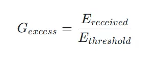
If Excess Gain > 1, the sensor provides a stable output. In heavy dust environments, engineers must select models with an excess gain of 10 to 100 times (such as through-beam types) to compensate for energy loss caused by the medium in the sensing path.
Photoelectric Sensor Types: Complete Classification
Major types of photoelectric sensors are classified according to the Optical Axis Configuration and the interaction with the target object. Engineers need a profound knowledge of these sensing modes to choose between proximity sensors and long-range optics:
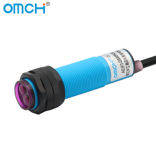
- Through-Beam: The Pinnacle of Long-Range & High Redundancy
Through-beam sensors are physical devices that physically separate the Emitter and Receiver to form a straight optical axis between them.
- Deep Mechanism: The effective beam is directed into the receiving lens without any loss of reflection, resulting in the highest possible signal strength. Because it utilizes the entire effective beam, it is nearly independent of the color or surface conditions of the target.
- Engineering Detail: When installing long-distance through-beams (e.g., 50m to 100m), one must account for Diffraction. If a tiny target obstructs less than 30% of the beam, light waves may “bend” around the object like water around a stone, preventing the receiver from detecting a change. In such cases, a “Slit” (aperture) must be added to compress the beam diameter, or a laser source should be used.
- Retro-reflective: Spatial Balance & Polarization Filtering
The emitter and receiver are built into a single side, and the beam is returned by a reflector (consisting of an infinite number of micro-prisms or corner cubes).
- Polarization: This is a high-end variation. Standard retro-reflective sensors are easily false-triggered by highly reflective mirror-like surfaces (like polished glass or stainless steel). Advanced sensors feature built-in, mutually perpendicular polarizing filters.
- Physical Filtering Logic: Horizontal polarized light emitted by the sensor is “depolarized” into vertical polarized light by the reflector, allowing it to pass through the receiver’s filter. However, light reflected off a mirror-like target maintains its phase and is blocked by the filter. This phase-recognition mechanism eliminates mirror interference at the physical root.
- Diffuse-reflective: The Gamble of Flexibility vs. Material
This mode utilizes the scattered light reflected directly off the target’s surface. It is the easiest to install but the most dependent on material properties.
- Energy Modeling & Attenuation: The detection distance D is non-linearly proportional to the target’s reflectivity rho. Standard detection distances are usually defined based on white paper with 90% reflectivity. If detecting black rubber or carbon fiber (reflectivity approx 6%-10%), the detection distance drops off a cliff.
- Application Boundary: Engineers must consult “Material Correction Factor Tables.”
- Background Suppression (BGS): Spatial Geometry Measurement
A development of diffuse technology, BGS does not judge on the light intensity, but on the Triangulation Principle to ignore background objects.
- Physical Structure: The receiver uses a CMOS or PSD (Position Sensitive Device) array. It determines distance by detecting the change in the physical position of the reflected light spot on the internal array.
- Core Value: It can precisely “cut off” the background. Although the target may be placed directly in front of a larger reflective metal frame that is brighter, the sensor will not go off unless the object is in the preset sensing range. It is the sole constant answer to the dilemma of the dark object on a bright background.
- Convergent Beam: Precision for Tiny Gaps and Thin Sheets
Through a specialized lens design, the emitted light and the receiver’s fields of view are forced to intersect at a specific, tiny focal point, offering higher precision.
- Technical Feature: It only responds to objects at the focal point (e.g., fixed at 20mm).
- Practical Use: Ideal for detecting component heights on PCBs, wafer edges, or distinguishing layers of thin film in extremely confined spaces.
- Clear Object Detection: Optimized for High-Transparency Materials
Particularly created to work with such materials as high-clarity glass, PET bottles, or transparent films.
- Principle: Utilizes more sensitive optical circuitry and automatic compensation technology. It may be triggered when the beam of light is attenuated by a transparent object by a mere 10 percent.
- Automatic Threshold Control (ATC): These sensors track gradual energy drops caused by enough lens contamination and automatically adjust the alarm threshold, preventing production line shutdowns due to minor buildup of dirt.
- Fiber Optic: Digital Extension for Extreme Environments
Uses plastic or glass fibers to bend the beam of light to the point of detection, and the amplifier (electronics) is mounted remotely.
- Engineering Value: The fiber heads are free of any electronic parts and can be used at temperatures up to 300 celsius. Fiber tips may be as thin as a needle (diameter <1mm).
- Electromagnetic Immunity: Since it transmits pure light signals, it offers unparalleled stability in environments with heavy EMI, explosive risks, or high vacuum.
- Area / Light Grid: Error-Proofing and Safety Protection
Composed of an array of multiple through-beam axes, forming a two-dimensional detection plane.
- Logical Function: It no longer detects a single “point” but a “plane.” Commonly used in logistics to detect irregularly shaped packages or as Safety Light Curtains for machinery, utilizing multi-axis logic for redundancy and safety.
Solving Complex Challenges with BGS Sensors
The BGS technology is the black technology of the diffuse world. It raises the sensor dimension of light intensity measurement to spatial geometry measurement.
Traditional diffuse sensors are unable to differentiate between an object that is near and dark and an object that is far and bright due to the possibility of the light intensity reflected back to the sensor being the same. BGS sensors resolve this through Triangulation.
As an object travels in the range of the set, the physical location of the reflected light on the CMOS varies. This displacement is calculated by the internal high-speed DSP chip to get the precise coordinates of the object.
- Physical Advantage: Regardless of whether the object is light-absorbing black or reflective white, as long as its physical position is beyond the preset “Cut-off Distance,” the sensor remains silent. This is the only stable solution when mounting on the side of a conveyor belt with a vibrating metal frame in the background.
Specialized Solutions for Common Industries

There is no universal sensor in the actual world of industrial automation. The industries require extreme physical durability, optical frequencies, and anti-interference algorithms.
Glass & Packaging – The Transparent Challenge
The largest headache when identifying high-quality crystal glass or high-transparency PET packaging is that light penetrates through the target almost 100 percent, and the receiver has insignificant energy variations.
- Pain Point: Standard retro-reflective sensors may only see a 5% drop in light when glass is present. Any minor dust can cause “false passes” or signal chatter.
- Deep Tech Solutions:
- Low Hysteresis Algorithms: Specialized sensors capable of capturing light intensity drops as low as 10%.
- DPAC Adaptive Technology: Dust accumulation causes signal drift over time. DPAC allows the sensor to automatically redefine the “empty” baseline, ensuring the threshold stays relative to the background and avoiding false alarms.
- Coaxial Optical Structure: To prevent refraction errors from bottle vibration, coaxial sensors (where emission and reception are on the exact same line) eliminate blind spots and ensure precision on bottle necks or bottoms.
Food & Pharma – Extreme Hygiene & High-Pressure Washdown
The test here isn’t detection difficulty, but “survivability.” These are the environments that are full of chemical cleaners of high concentration and frequent hot water washes.
- Pain Point: Standard plastic housings crack under 80°C high-pressure washdowns or corrode under strong acids/alkalis.
- Deep Tech Solutions:
- IP69K & 316L Stainless Steel: Housings should be made of medical-grade 316L stainless steel that can be welded with a laser. This can resist 100 bar pressure and does not leave any dead zones where bacteria can grow.
- Glass Lenses & No-Label Design: Swap plastic for chemically resistant tempered glass. Use laser marking instead of stickers to prevent labels from peeling off and contaminating the food line.
- Wide Temperature Range: For cold chain packaging, anti-frosting features are vital to ensure lenses don’t fog up during frequent cold/heat cycles.
Heavy Industry & Metal – High Heat, Dust, and Oil
Steel, mining, and metalworking environments are laden with conductive dust, coolant spray, and temperatures reaching hundreds of degrees.
- Pain Point: Circuit boards fail under heat, and lenses are quickly blinded by thick oil or grime.
- Deep Tech Solutions:
- Remote Fiber Separation: Place the fragile amplifier in a remote electrical cabinet and use stainless-steel armored glass fiber heads to reach the core heat zone (capable of withstanding 350 celsius).
- Air Blow Hoods: Install a constant pressure air curtain in front of the lens. This uses fluid dynamics to prevent dust and oil droplets from adhering, extending cleaning cycles by over 10 times.
- High Redundancy Through-Beam: In smoky/dusty areas, ultra-high excess gain through-beams can be used, which can be triggered even when 90% of the beam is obscured by haze.
Logistics & Warehousing – Large-Scale Sensing
Logistics emphasizes high-speed sorting, ambient light immunity, and ease of installation.
- Pain Point: Intense LED warehouse lighting, fast-moving black parcels, and irregularly shaped pallets.
- Deep Tech Solutions:
- Area Detection Light Grids: Light grids are used in the case of irregular parcels (like soft polybags) to scan the entire plane and the entire plane is counted properly regardless of the orientation of the package.
- Anti-interference Encoding: When hundreds of sensors are mounted side-by-side, crosstalk is a killer. Modern sensors have unique pulse encoding to ensure that they only respond to their light.
- BGS Conveyor Cut-off: Do not feel the high-speed black conveyor background to reduce the data load on the PLC.
Laser vs. LED: Choosing the Right Light Source
Choosing a light source is a trade-off between Energy Density and Tolerance.
LED Source (Incoherent Light): The Bedrock of Stability
- Physical Properties: The light spot diverges in a cone shape. The spot is typically 10-15mm wide at 100mm. This roughness is in fact a colossal plus in most situations.
- Logic & Benefits:
- Vibration Tolerance: Since the spot is large, the receiver still receives sufficient signal when the sensor bracket vibrates a little when operating at high speed.
- Ignoring Flaws: Since the spot is large, the receiver still receives sufficient signal when the sensor bracket vibrates a little when operating at high speed.
- Lifespan: LED sensors are simple to use and more tolerant to heat, which is why they are the best choice in 24/7 logistics lines.
Laser Source (Coherent Light): Extreme Precision & Reach
Laser light features Collimation and monochromaticity.
- Physical Properties: The beam is nearly parallel (divergence <0.1 degree). Even at 10 meters, the spot remains at millimeter level.
- Logic & Scenarios:
- Sub-millimeter Positioning: Detecting 0.5mm wafers or 0.5mm Eye Marks on high-speed (600m/min) packaging machines.
- Long Range: Maintains a high signal-to-noise ratio over 100 meters for perimeter alarms.
Comparison Table: Data-Driven Decision Making
| Key Factor | LED Sensor (Standard) | Laser Sensor (Precision) |
| Spot Diameter (@ 1m) | Approx. 30mm – 50mm | Approx. 1.5mm – 2.5mm |
| Repeatability | Medium (± 1mm ~ 3mm) | Extreme (± 0.05mm ~ 0.2mm) |
| Background Immunity | Moderate | Superior (Best with BGS) |
| Alignment Difficulty | Very Low (Easy to adjust) | Very High (Tiny shifts cause failure) |
| Safety Standard | No restrictions (Normal light) | Class 1 (Safe) or Class 2 (Visible) |
| Typical Environment | Packaging, Logistics, Counting | Semiconductors, Small parts, Precise gaps |
Critical Selection Factors: Beyond Just Distance and Speed
To achieve “zero false alarms” and “long service life,” you must look at the variables hidden behind the datasheet.
- Target Physical Properties: Defining the Sensing Ceiling
- Spectral Reflectance & Color Attenuation: In diffuse sensing, a black target reflects only 6%-10% of light. When the background is bright metal, then you have to use BGS so that the background does not overwhelm the target signal.
- Transparency & Beam Penetration: To detect a small decrease in energy (10 percent) in ultra-clear glass or film, Low Hysteresis and ATC sensors are required.
- Surface Geometry: Glossy spheres or slopes deflect light. In such situations, big-spot LED sources are not as dangerous as precision lasers to guarantee that some light is reflected back to the receiver.
- Environmental “Noise” & Excess Gain: Defining Stability
- Excess Gain Curve: Don’t just look at the rated distance; look at the gain at that distance. In dusty zones, you need a model where the gain is still >10 or even >50 at the target distance. This ensures the system works even if the lens is 50% covered in grime.
- Ambient Light Immunity: Factory skylights or high-frequency LEDs can saturate cheap receivers. Professional sensors use synchronous pulse modulation to stay accurate under 30,000 Lux.
- EMC: High-power motor cables generate interference. Ensure your sensors have reinforced shielding and surge protection.
- Mechanical Margins & Hysteresis Control
- Hysteresis: The physical gap between the “On” and “Off” points. For vibrating or rough targets, you need a hysteresis of 10%-20% of the sensing distance to prevent signal “chattering.”
- Spatial Constraints: In tight robotic arms, switch to Fiber Optic or Side-view designs. Fiber heads are easy to handle space problems and mechanical blind spots.
- Dynamic Response & Logic Consistency
- Frequency & Duty Cycle: When dealing with small objects (e.g. 1mm pins) at high frequencies, make sure that the sensor frequency response is rapid enough to sample the target several times during the passing window.
- Output Protection: Verify that the output has Short-circuit and Reverse Polarity Protection. This prevents a simple wiring mistake from frying an expensive controller.
Why Supply Chain Soft Power is a Core Standard?
Supply chain certainty is the final tie-breaker when technical specifications match. This is the reason why OMCH has emerged as the best option for more than 72,000 customers worldwide.
- Cycle-to-cycle Reliability: OMCH was established in 1986. We have experienced all the failures that can be encountered in the automation world with 40 years of heritage. This experience is converted into design redundancy, which guarantees consistent operation in response to changes in voltage or extreme temperature variations.
- One-Stop Synergy 3,000+ SKUs: No patchwork builds. OMCH has more than 3,000 models, including photoelectric and proximity switches, power supplies, relays, and pneumatic parts. Using OMCH will ensure that your cables and brackets are the right size, and you will not have any size or protocol mismatch.
- International Certification Authority: Certifications are crucial to equipment exporters. OMCH products are ISO9001, CE, RoHS, CCC, and IEC compliant. These are not mere logos, they are quality assurances that have been developed by 7 production lines and a rigorous IQC/IPQC/OQC 3-level inspection procedure in our 8,000 sqm factory.
- The Physical Distance of Service: The production of industry cannot cease. OMCH has sales networks in more than 100 countries, and it offers 24/7 technical support. It can be an assembly plant in Asia or a packaging line in Europe, but our 1-year warranty and quick delivery (15 days on samples, 45 days on orders) will give them that necessary psychological safety.
Output Types Explained: NPN vs. PNP and Light-ON vs. Dark-ON
Correct electrical pairing is the prerequisite for functionality.
- Transistor Logic: NPN vs. PNP
- NPN (Sinking): The load connects between the positive rail and the output. When triggered, the sensor pulls the output to ground (0V). Common in Asia.
- PNP (Sourcing): The load connects between the negative rail and the output. When triggered, the sensor pumps +24V to the load. Common in Europe for safety (a short-to-ground won’t trigger a false signal).
- Action Modes: Light-ON vs. Dark-ON
- Light-ON: Output closes when the receiver sees light above the threshold.
- Dark-ON: Output closes when the receiver is “dark” (beam blocked).
- In through-beam safety applications, Light-ON is preferred so that a broken power cable is interpreted as a “blocked” state, stopping the machine.
Future-Proofing with IO-Link and Smart Diagnostics

The future is Data. IO-Link has transformed sensors from switches into data nodes.
- Digital Parameter Assignment: The technician does not need to use a screwdriver to adjust a potentiometer, the PLC can move the new sensing distances to all the sensors in 1 second during a product changeover.
- Predictive Maintenance: Sensors are able to provide their Gain Margin feedback. In case the grime decreases signal by 100 to 40 percent, the sensor transmits a clean me request through IO-Link before the line actually fails.
Quick Troubleshooting: Common Setup Mistakes
- Crosstalk: Two through-beams installed side-by-side where Emitter A hits Receiver B.
Solution: Cross-mount them (Emitter next to Receiver) or use sensors with mutually exclusive frequencies.
- Small Object Diffraction: Very thin wires can allow light to “bend” around them.
Solution: Use a laser source or add an aperture slit.
- Gain Saturation: In a retro-reflective system, the reflector is too close and the energy can saturate the amplifier and it will not be able to see high-transparency objects.
Solution: Turn down sensitivity or use a sensor with Auto Gain Control.


